In-Place Interface Topology
In an in-place topology, there is no physical separation in space between the two boundaries comprising the interface.
Furthermore, there is no requirement that the two boundaries have the same perimeter. After the imprinting (for surface remeshing), or intersection (for volume meshes used in an analysis) occurs the original boundaries maintain their boundary type and retain whatever surface area remains (if any).
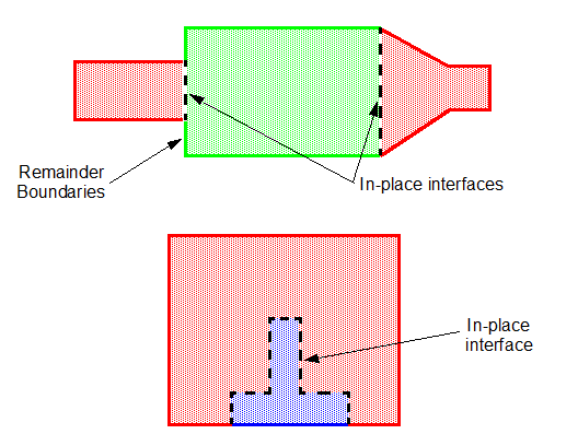
The figure below shows different examples of in-place interfaces. The shaded red, green, and blue areas represent different mesh regions, such as porous/non-porous or fluid/solid combinations. The dotted black line in each case would represent the in-place interface that would be created between the coincident boundaries for each region. Where the areas of the original boundaries differ then remainder boundaries are produced.

When the in-place interface type is used with the surface remesher, an attempt is made at producing a conformal mesh on each side of the interface. In other words, if successful, the two boundaries when mapped from one to the other match identically in terms of the vertex locations and face topologies. The matching results in a higher-quality volume mesh definition for the analysis stage.
The option to produce a conformal mesh is automatically initiated when an in-place type interface has been created and the surface remesher is used afterwards. If it is not successful, then the meshing process is terminated and an error message is produced indicating the nature of the problem.