Computing the Surface Sensitivity
The surface sensitivity model allows you to identify which areas of geometry are most critical to the cost functions of interest. The sensitivity field can be further used in computing displacements that are then used to deform the mesh for shape optimization. To reduce computation time compared to the mesh sensitivity, the model computes approximate sensitivities with respect to surface position for the selected adjoint cost functions Surface Sensitivity of [cost function] w.r.t Position.
Compared with the mesh sensitivity, the surface sensitivity computation scales better for large simulations. In addition, Surface Sensitivity Filtering option is used to mitigate the effect of noisy derivatives on the surface. If you intend to directly manipulate the surface during optimization or are running an initial assessment of which areas to modify, the surface sensitivity combined with filtering is the better choice.
The surface sensitivity is computed using the spring analogy deformation method operating in adjoint mode. This serves as a lightweight faster-running substitute for the mesh deformation adjoint and mesh sensitivity. You can consider the surface sensitivity settings on each boundary to be analogous to mesh deformation settings. There are two available surface sensitivity settings in Simcenter STAR-CCM+.
To run a shape optimization simulation using surface sensitivity on boundaries, follow the steps in Shape Optimization using Surface Sensitivities.
Before you can compute surface sensitivity, you must have the following:- Converged primal flow solution
- Converged adjoint solution with respect to the defined cost functions
- Right-click the node and select Surface Sensitivity from the Optional Models group box.
-
To specify surface sensitivity boundary settings, select the node and set Option to one of the following:
- Active—is equivalent to a specified boundary condition in mesh deformation. When activated, the Active Surface Sensitivity node is added to . This option is activated by default.
- Passive—equivalent to a floating boundary condition in mesh deformation. Similar to the interior mesh elements, passive boundary surfaces float based on prescribed displacements of active surfaces.

-
To specify if the parameter sensitivity for CAD includes the active surface,
select the node and set Option to one of the following:
- Displacement—the surface sensitivity contribution is included in the Compute Parameter Sensitivity calculation to obtain CAD sensitivities. This option is the default.
- Fixed—the surface sensitivity contribution is excluded from the Compute Parameter Sensitivity calculation to obtain CAD sensitivities.
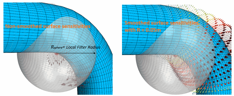
In the computed surface sensitivity, noise and sharp variations appear due to a combination of the discrete nature of the problem, the mesh quality, and numerical error. Before applying surface sensitivity in a shape optimization, you are advised to smooth the values using the Surface Sensitivity Filtering option. The filter ensures that the surface sensitivity field contains no sharp variations on a length scale smaller than the specified filter radius. The filter permits limiting the size of geometrical features that are introduced during the optimization. For each face on which surface sensitivity is computed, filtering causes Simcenter STAR-CCM+ to define a virtual sphere that is located around the face centroid with a radius defined by either the Global Filter Radius. Simcenter STAR-CCM+ computes an inverse-weighted average of all sensitivity values from the faces found within the sphere.
-
Activate surface sensitivity filtering:
-
If required, define a local filter radius on a boundary:
-
Set the surfaces to zero surface sensitivity:
- Select the node and set Filter Option to Excluded Surface.
- For a fixed wall boundary, if the Morpher Specification is set to Fixed, the Filter Option should also be set to Excluded Surface.
-
To toggle between active and passive behaviour for an interface in the surface
sensitivity calculation, select the node and set Option to one of the following:
- Active—the surface sensitivity solver computes a single set of values which appears on both boundaries of the interface.
- Passive—the surface sensitivity behaves as if the domain were not separated by an interface. The surface sensitivity of two regions connected by a passive interface should match the solution calculated on a single region without an interface. The results are not identical, due to the formulation of the surface sensitivity solver, but they are very close. For a passive interface, the surface sensitivity does not appear on the interface boundaries.
- To calculate the surface sensitivity for all active cost functions, right-click the node and select Compute Surface Sensitivity.
- To execute the surface sensitivity for a specific cost functions, right-click the node and select Compute Surface Sensitivity.
- To visualize the surface sensitivity field, refer to Visualizing the Surface Sensitivity.
For more information, see Adjoint Theory: Surface Sensitivity.