Importing Geometry into a 3D-CAD Model
You can import solid and sheet (zero thickness) bodies into 3D-CAD. During the import process, you are presented with the option to include or omit sheet bodies. The import option is available within the main Simcenter STAR-CCM+ window as well as within the 3D-CAD environment itself.
3D-CAD supports the following CAD file formats:
- .prt/.asm - Creo - Pro/E files
- .par/.asm - Solid Edge files
- .3dxml - CATIA V6/3DExperience files
- .prt - NX files
- .ipt/.iam - Inventor files
- .3dm - Rhinoceros 3D Model files
- .sat/.sab - ACIS files
- .jt - JT Open files
- .xml/.plmxml - PLMXML files
- .cgr - CATIA CGR files
- .ifc - Industry Foundation files
- .dbs - STAR-CD Surface Mesh files
- .inp - STAR-CD Shell Input files
- .stl - Stereolithography files
- .x_t/.x_b - Parasolid Transmit files
- .iges/.igs - IGES files
- .step/.stp - STEP files
- .model/.exp/.session - CATIA V4 files
- .catpart/.catproduct - CATIA V5 files
- .sldprt/.sldasm - SolidWorks files
Importing Geometry into 3D-CAD
Importing a geometry into the 3D-CAD module allows you to repair or modify it before running a simulation. Simcenter STAR-CCM+ allows you to import multiple CAD files at the same time, including multi-surface binary STL files (where multiple STL binary data is concatenated into a single STL binary file). You can also choose whether to import the geometry into an existing 3D-CAD model (if one exists in the simulation) or assign it to a new 3D-CAD model. You can also import CAD geometry directly to the geometry parts tree (see Importing Surface Data into Simcenter STAR-CCM+ ).
All imported bodies within 3D-CAD must fit inside a box with dimensions 1000 m x 1000 m x 1000 m, and a center [0, 0, 0] m, m, m. This means that a single body cannot be larger than 1000 m in any direction. Issues can occur in the downstream operations if the domain is close to this limit. For some features this limit is reduced to 500 m when other dimensions have already reached the maximum limit of 1000 m.
To import a CAD geometry into 3D-CAD:
- Create a new Simcenter STAR-CCM+ simulation.
- Launch the import action using one of the following options:
- Select .
- From the Mesh Generation toolbar, click
 (Import CAD Model into 3D-CAD....
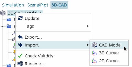
 - If you want to import a geometry inside the 3D-CAD modeler, right-click on the 3D-CAD Model node at the top of the model tree and select . For more information on how to open the 3D-CAD modeler, see Creating a 3D-CAD Model.

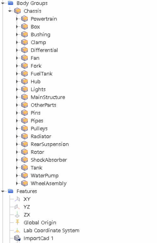
The 3D-CAD environment launches and a 3D-CAD model is created. Within 3D-CAD, an object tree that is specific to the 3D-CAD model is displayed. This tree contains Body Groups, Features, Design Filters, and Design Parameters nodes.
- Select the CAD files to import.
- Choose the import options. See 3D-CAD Import Options.
- To begin the import process, click Open.
For multi-surface binary STL files, Simcenter STAR-CCM+ imports each surface as a sheet body. In 3D-CAD part surface names are imported automatically using the first word of the binary data headers as the surface name.
To import Creo .prt or .asm file containing metadata, it is recommended that you import the files directly into 3D-CAD using the Siemens Adapter for Creo instead of, first, exporting the geometry to a .step file.

You can change the way the bodies are organized in the 3D-CAD tree to appear as a flat list. See Controlling how Bodies are Organized in the 3D-CAD Tree.
The import process adds an ImportCad node to the 3D-CAD feature tree.
If any errors are encountered during the import, the operation completes with a Partially Successful status. For example, if a valid CAD file does not import bodies into 3D-CAD, the import operation is partially successful. A  symbol appears next to the partially successful operation in the 3D-CAD feature tree.
To undo the import, delete the ImportCad feature.
Once the geometry is imported, you can modify it using the tools available in 3D-CAD.
Modifying Imported Geometry
- Adding features to the model by creating more geometries.
- Extracting an internal or external volume in order to analyze the internal or external flow.
- Defeaturing the geometry by deleting bodies, and using extruded and revolved cuts.
- Imprinting a profile on the surface using the imprint operation.
- Renaming faces so that they are defined as separate surfaces when the model is used in the simulation.
3D-CAD Import Options
Select the appropriate import options for your CAD geometry.
| Option | Description | ||
|---|---|---|---|
| Import Sheet Bodies | When activated, imports sheet bodies into 3D-CAD. Deactivate this option if you want to ignore sheet bodies and only import solid bodies. | ||
| Import Faceted Bodies | When activated, imports faceted data into 3D-CAD from tessellated file formats. If you are importing a CAD file format, the geometry is converted into faceted bodies and then imported into 3D-CAD as a faceted solid or faceted sheet. If there is any conversion error, the geometry is imported as a solid or sheets. | ||
| Import Metadata | When activated, imports the metadata associated with the bodies or body groups. Applies only to PLMXML, NX or JT Open files. | ||
| Check Body Validity | When activated, checks the validity of the CAD geometry during the import process. See Checking Geometry Validity. | ||
| Repair Invalid Bodies | When activated, attempts to repair invalid bodies during the import process. This option invokes both the Parasolid healing option from the CAD translator, and the automatic healing from the CAD Repair tool. Parasolid healing only takes place when you activate this option and import the CAD model into Simcenter STAR-CCM+. If you import the CAD model without activating this option, and subsequently run CAD repair manually, only the CAD repair healing is executed. See Repair Invalid Bodies. | ||
| Ignore Face Names | When activated, ignores the names of faces, edges, and vertices in the imported CAD geometry. Some CAD formats can contain unique names for every face, edge, and vertex. Large or complex CAD geometries can have a significant number of named faces, edges, and vertices. Importing such files into 3D-CAD can affect the performance of 3D-CAD. When deactivated, imports face names and colors. For CATIA, the face name and color is obtained from the parent feature of the face and not the face itself. | ||
| Ignore Unnamed Face Colors | When activated, ignores the unnamed face colors in the imported CAD geometry. When deactivated, imports the unnamed face colors, while following Simcenter STAR-CCM+ internal naming convention. | ||
| Simplify Assembly Structure | Attempts to match the assembly structure with the file in the native CAD package. | ||
| Split Periodic Faces | When activated, splits the periodic faces in the imported CAD geometry. For example, periodic faces such as cylindrical faces are split into two semi-cylindrical faces. | ||
| Create New 3D-CAD Model | When activated, allows you to create a new 3D-CAD model. This option appears as read-only if you are working inside a 3D-CAD modeler session.
| ||
| CAD Model | Allows you to import a geometry into an existing 3D-CAD model. This option appears as read-only if you are working inside a 3D-CAD modeler session.
| ||
| Importer | Siemens Adapter supports CATIA V5, CATIA V4, CATIA V6/3DExperience, CGR, NX, Solid Edge (Windows only), JT, SolidWorks, Inventor, Creo, STEP, IGES, ACIS, and IFC import. For CATIA and STEP files. No additional CAD Exchange Reader licenses are required for the NX, Solid Edge, IGES, STEP, or JT Adapters. All other adapters require the CAD Simcenter STAR-CCM+ Exchange license. When using Siemens NX Adapter import option, Simcenter STAR-CCM+ imports multi-bodied NX CAD parts as leaf composite body groups. |