The Turbo Slicing Surface Panel
The options to control the neutral surface parameters are found in this panel.
- Input Type
- Specifies the type of input you want to
create neutral surfaces from. All blade types (Axial, Axial Mixed Plane,
Radial, and Radial Diffuser) are supported. There are two input options for
this:
- Blade Faces—specifies the faces that make up the blade through which the neutral surface must pass. The neutral surface is created based on the selected blade faces. As a guideline, select all the faces that form a loop around the blade surfaces. If the blades contain cooling features, you can ignore these. If the blade contains small patches, you are advised to omit these from the blade selection, as they can cause problems.
- Blade Sketches —specifies the blade sketches that generate the blade faces through which the neutral surface must pass. The neutral surface is created based on the sketch profiles of the selected blade.
- Blade Type
- Specifies the type of geometry you want to
generate the neutral surface on. There are four options for this:
- Axial—the inlet and outlet faces on the geometry are parallel to each other and perpendicular to the axis of rotation. The inlet and outlet faces must be planar.
- Axial Mixed Plane— is neither axial or radial with a relatively flat inlet face, and the outlet face may be any bending face. The sketches used to construct the blade and the corresponding leading and trailing edges should be used for the creation of slicing surfaces.
- Radial—the inlet and outlet faces on the geometry are perpendicular to each other. The inlet face is typically planar and normal to the axis of revolution.
- Radial Diffuser—the inlet and outlet faces on the geometry are concentric or almost concentric. The inlet and outlet faces must have the same, or almost the same, axis of revolution.
- Blade Face or Blade Sketches
- Specifies the faces or sketches that make up the blade.
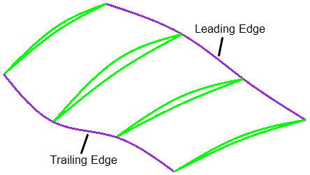
- Leading/Trailing Sketches
- Specifies the sketches that intersect with the sketch profile of the leading
edge and trailing edge.
- Hub Faces
- Specifies the faces that make up the hub. Select the faces that surround the blade of interest.
- Shroud Faces
- Specifies the faces that make up the shroud. Select the faces that surround the blade of interest.
- Inlet faces
- Specifies the faces that make up the inlet.
- Outlet Faces
- Specifies the faces that make up the outlet.
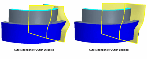
- Auto Extend Inlet/Outlet
- Activate Auto Extend
Inlet/Outlet for geometries containing either:
- Two or more small inlets or outlets.
- An inlet or outlet face which produces an angle less than 20 degrees to the axis of revolution of the blade (non-planar faces).
- Surface Resolution
- Specifies the spanwise (hub to shroud) resolution of the grid that is used to define the neutral surface.
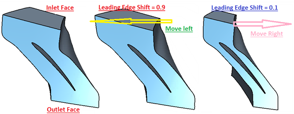
- Leading Edge/Inlet Transition Shift (Axial Blade Type Only)
- Specifies the transition of the neutral surface from the inlet to the
leading edge of the selected blade. The neutral surface is constrained to be
normal to the inlet plane. This parameter defines the non-dimensional
location between the inlet and the blade leading edge where the sheet
transitions to satisfy the normal constraint. The valid range is from 0.0 to
1.0, from the leading edge to the inlet. The smaller the value, the sharper
the transition.
- Trailing Edge/Outlet Transition Shift (Axial Blade Type Only)
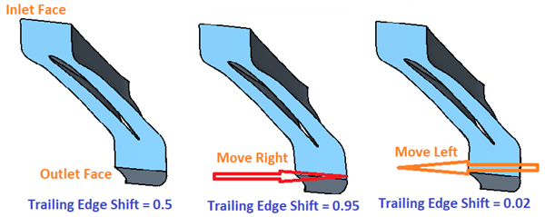
- Specifies the transition of the neutral surface from the outlet to the trailing edge of the selected blade. The neutral surface is constrained to be normal to the outlet plane. This parameter defines the non-dimensional location between the outlet and the trailing edge of the blade where the sheet transitions to satisfy the normal constraint. The valid range is from 0.0 to 1.0, from the trailing edge to the outlet. The smaller the value, the sharper the transition.
- Surface Direction (Radial or Radial Diffuser Blade Types Only.
- Specifies how the neutral surface is generated on the leading edge of the
selected blade. Select the option that returns the best neutral surface.
There are two options for this:
- Leading Edge to Inlet—The neutral surface extends
from the leading edge of the selected blade to the inlet
surface.
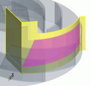
- Leading Edge to Axis—The neutral surface extends
from the leading edge of the selected blade to the axis of
revolution.
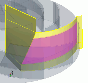
- Leading Edge to Inlet—The neutral surface extends
from the leading edge of the selected blade to the inlet
surface.
