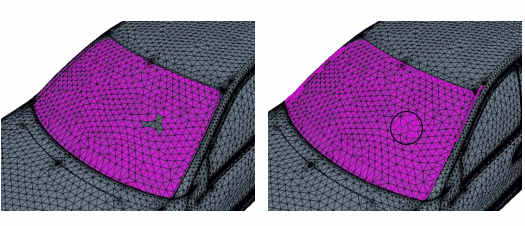
Classifying Surfaces
In many cases, different surfaces of a geometry part require different mesh settings, for example, a different number of prism layers for internal and external surfaces. In Surface Repair, you can Classify faces based on specified criteria and create corresponding part surfaces. This classification process is suitable for regular geometries with well defined angles.
- Source Distance
- Visibility Angle
- Sharp Angle
You can construct the Classified Faces subset gradually using multiple target points or you can use a single target point. The number of target points you require depends on the surface you want to cover and the specified classification settings. You are recommended to classify one part at a time.
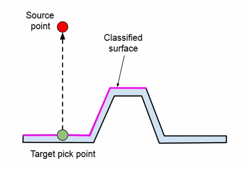
If, however, the dihedral angle between adjacent faces is greater than the Sharp Angle, those faces are not included in the classification subset. For more information, see Classify Surfaces.
- Launch Surface Repair.
-
In the Surface Repair scene, display the
surfaces that you want to classify.
To reduce the time it takes to visualize the geometry in the Surface Repair scene and speed up the classification process, only display the parts that you wish to classify.
-
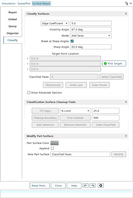
In the Surface Repair tab, select Classify.
-
Set Color Mode to Face
Normal.
The Face Normal color mode colors all faces with a positive face normal in green and faces with a negative face normal in red. For more information, see Color Modes.
- If the surface is oriented incorrectly, activate Show Advanced Options, then activate Invert Source Direction.
-
Select Pick Target... and, in the Surface Repair scene, place target points on the surface you
wish to classify.
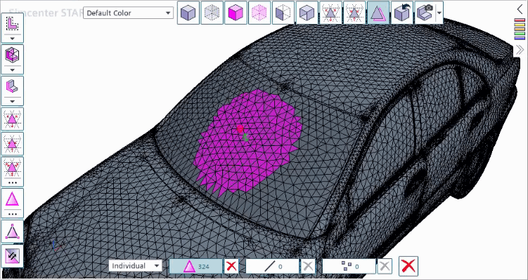
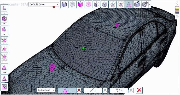
In the scene, target points appear in green, source points in red, and the faces included in the Classified Faces subset are highlighted in magenta.To completely cover the desired surface area, you can use one of the following methods:- Place multiple target points along the surface.
For each local point you can define an individual Source Distance, Visibility Angle, and Sharp Angle.
To classify the surface, start from the center of the surface and trace a path around its edge. When you trace the path, maintain a symmetrical pattern and the same distance between points along the geometry edge. In general, curved surfaces require a smaller Visibility Angle compared to planar surfaces. This ensures the required faces are included in the classification subset. For enclosed or tight areas in the geometry, it is recommended you reduce the Source Distance to around one or two face edge lengths. For more information, see Classification Tool Reference.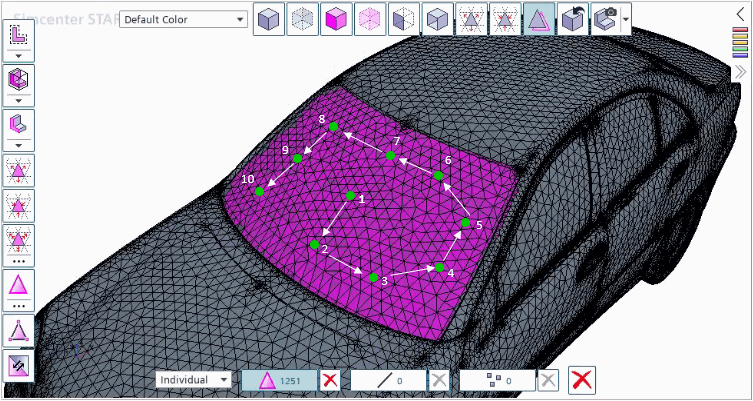
注 New target points can be positioned on faces already included in the Classified Faces subset. - Specify a single target point at the center of the
surface.To maximize the number of faces included in the classification subset it is recommended you set the source distance (see Source Distance) to a distance greater than, but approximately on the same scale, as the maximum dimension of the part assembly, and set the Visibility Angle to 90.0 deg.
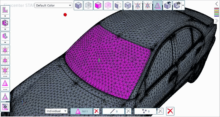
注 Simcenter STAR-CCM+ automatically clears the classification subset if you use any mesh repair tools during the classification process.
- Place multiple target points along the surface.
-
To cancel the Pick Target... operation, press
Esc. -
If the outcome of the classification is not as expected:
- Modify the classification settings, and select (Re)Classify.
- Select Undo Last, and select a new target point location.
-
Deactivate Auto Classify on Pick.
If Auto Classify on Pick is deactivated, to classify the surface, select (Re)Classify.
-
To improve the visibility of the surfaces with faces selected, activate
 (Toggle face, edge, and vertex selection
depth control).
For more information, see Embedded Tools Reference.
-
To identify and add these faces:
Alternatively, to fill the gaps automatically during classification, activate the Auto Fill Gaps advanced option. When using this option, set the correct face count properties before you select the target points. If you select Undo Last with Auto Fill Gaps activated, Simcenter STAR-CCM+ undoes both the fill gaps and classification result.
- If some gaps remain unfilled, repeat the process.
-
Select Cleanup Boundary.

This option adds or removes faces along the boundary. A face is only identified by the clean-up process if:- The face has more than two (triangle) or three (quadrilateral) adjacent faces which do not belong to the same subset (classified or unclassified) as the face in question.
- The classification subset contains more than ten perimeter edges.
-
During the classification process, Simcenter STAR-CCM+ can also include isolated faces (islands) in the
classification subset. To identify and remove any unwanted isolated faces from
the classification subset:
- To include individual faces or entire surfaces in the classification subset, in the Surface Repair scene, select the required surface and select Add Selection.
-
To create a new part surface from the classification subset, choose one of the
following options:
- Set the New Part Surface name and
Part Surface Color, then select
Modify.
This method creates a single part surface for all faces in the Classified Faces subset.
- Activate Append and set the Append Name, then select
Modify.
This approach maintains the existing part surface distribution, as it creates a new part surface for each classified surface. The name of the new part surfaces is the format [part surface name]_[append name]. The state of the append options is saved and restored in the simulation file.
- Set the New Part Surface name and
Part Surface Color, then select
Modify.
- To delete the source and target points from the Surface Repair scene, select Clear Points.
- To restart the classification process, select Clear Classified.
-
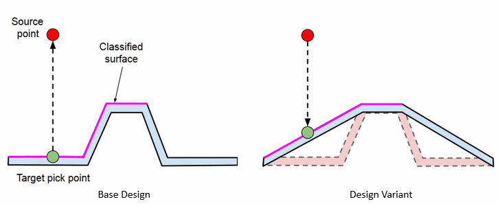
To record the source point, in the Advanced Options, activate Journal Source Point.
With the Journal Source Point property activated, the Invert Source Direction is ignored and Simcenter STAR-CCM+ automatically determines the normal direction of target surface and automatically inverts the results for each classification as required.
