Query Tools Reference
Use the Query tools to get more information about entities in the geometry.
Vertex Query Tools
Vertex query diagnostics provide information specific to the vertex or vertices that are selected in the Graphics window.
 Vertex location(s) in laboratory and local systems
- By default, the location is defined relative to the laboratory coordinate system. An example report for a single vertex selection is provided below:
Vertex Coordinate Report (vertex 7977)
 Laboratory : [-0.148194 0.0483969 -0.0666961] (m)
When selecting multiple vertices, the query reports the list of coordinates and ID's of the selected vertices. There is no correlation between the Output list order and the vertices selection order.
You can also choose to report the vertex/vertices location relative to a local coordinate system by setting the coordinate system of the view. One method of changing the view coordinate system is to click the Save-Restore-Select views button and select View Coordinate System, followed by your choice of system: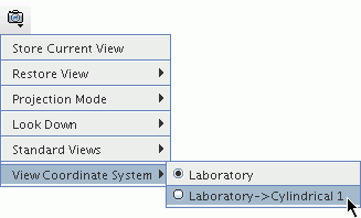
In this case, the query reports the vertex/vertices location relative to the selected local coordinate system and the laboratory coordinate system.Vertex Coordinate Report (vertex 7977) Laboratory : [-0.148194 0.0483969 -0.0666961] (m) Cylindrical 1 : [0.155896 2.82593 -0.0666961] (m,radian,m)  Distance Between Two Selected Vertices
- This query reports the distance between two vertices. It also reports the vertex IDs, locations, and the distance between the selected vertices in the x-, y-, and z-direction. By default these components are displayed relative to the laboratory coordinate system. However, if the scene view is set to a local coordinate system, the components are displayed in the output window relative to both coordinate systems. This query is available when you select only two vertices.
An example report is provided below:
Vertex Distance Report
 Distance = 0.339408687794 (m)
Laboratory (m):
 Vertex 3 : [-0.0563497297057 -0.03 0]
 Vertex 8 : [0.06 0.0779860997883 0.3]
 Components (dx dy dz): (0.116349729706 0.107986099788 0.3)
Caretesian 1 (m):
 Vertex 3 : [0.224019789825 0.00728642763607 0.157484804765]
 Vertex 8 : [-0.0611299627533 0.0256098352269 -0.0256875967843]
 Components (dx dy dz): (-0.285149752578 0.0183234075908 -0.183172401549)
Geometric Range of the Selected Vertices
- This query reports the minimum and maximum coordinate values (relative to the laboratory coordinate system) of a bounding-box that contains all selected vertices. It also reports the dimensions (change in coordinate value) of the bounding-box in the x-, y-, and z-direction. Select two or more vertices before this query becomes available.
An example report is provided below:
Vertex Geometry Range Report (m)
 Min. Global Value : [-0.155686 0.0982237 -0.120845]
 Max. Global Value : [-0.135411 0.1397 -0.0376828]
 Components : dx = 0.0202747
              dy = 0.0414763
              dz = 0.0831617
You can view the geometric range using local coordinate systems.
To select a local coordinate system, click
 (Save-Restore-Select Views) and select
. Cylindrical coordinate systems only report radial and axial ranges; angular ranges are not reported. Spherical coordinate systems only report radial ranges.
Edge Query Tools
Edge query diagnostics provide information specific to the edges selected in the Graphics window.
 Length of the Selected Edge(s)
- This query reports the length or total length of an edge or edges. For multiple edges, it also reports the minimum, maximum and average edge length. Select at least one edge before this query becomes available.
If only one edge is selected, the report appears as shown in the example below:
Length of edge 5334 is 0.0113075 (m)For multiple edges, the report appears as follows:Edge Lenght Report (m) Total Edge Length = 0.130005 Min. Edge Length = 9.72937e-005 Max. Edge Length = 0.0278163 Ave. Edge Length = 0.014445  Dihedral Angle of the Selected Edge(s)
- This query reports the dihedral angle of an edge, which is the angle between its adjacent faces. This query can report the angles for edges with more than two faces connected to it, for example non-manifold edges. For multiple edges, it reports the minimum, maximum and average dihedral angle, and the number of valid edges. Edges are considered invalid if they are free, as a dihedral angle cannot be calculated for such edges. Select at least one edge before this query becomes available.
When using Edge Dihedral Angle as a Threshold Diagnostic, manifold and non-manifold edges are selected according to the angle between the face normals of the connected faces of the edge. For non-manifold edges, the nearest neighbor faces are used for each angle calculation.
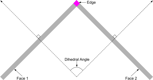
If only one edge is selected, the report appears as shown in the example below:Dihedral angle of edge 3175 is 0.0653701 (radian)For multiple edges, the report appears as follows:Edge Dihedral Angle Report (radian) No. of valid edges = 5 Min. Angle = 1.49012e-008 Max. Angle = 3.0761 Ave. Angle = 0.637921  Geometric Range of the Selected Edge(s)
- This query reports the minimum and maximum coordinate values (relative to the laboratory coordinate system) of a bounding-box that contains all selected edges. It also reports the dimensions (change in coordinate value) of the bounding-box in the x-, y-, and z-direction. Select at least one edge before this query becomes available.
An example report is provided below:
Edge Geometric Range Report (m)
 Min. Global Value : [0.0093659 -0.03175 -0.0404585]
 Max. Global Value : [0.1905 0.243205 0.0345574]
 Components : dx = 0.181134
              dy = 0.274955
              dz = 0.0750159
You can view the geometric range using local coordinate systems.
To select a local coordinate system, click
 (Save-Restore-Select Views) and select
. Cylindrical coordinate systems only report radial and axial ranges; angular ranges are not reported. Spherical coordinate systems only report radial ranges.
 Angle between two Selected Edges
- This query reports the angle
between two selected edges. It also reports the IDs of the two selected
edges, unit vectors calculated for each, interior angle between the vectors,
supplementary angle (180 degrees - interior angle) and whether a common
vertex was found. The selected edges can be connected (that is, share a
common vertex) or disconnected (no common vertex) in space. In the following example, the query contains two edges that shares a vertex:
Edge Angle Report (deg)
           Edge 56776 : Vector (0.460206 -0.881635 0.104551)
           Edge 56965 : Vector (0.945605  0.305563 0.111638)
           Interior Angle : 79.7787381205
           Supplementary Angle : 100.221261879
           Common vertex : true
If the edges are disconnected then the common vertex changes to:Edge Angle Report (deg) Edge 47170 : Vector (0.998383 -0.0354738 -0.0444134) Edge 47291 : Vector (-0.824778 0.556733 -0.102261) Intersection Angle #1 : 146.995721198 Intersection Angle #2 : 33.0041788022 Common vertex : false
Face Query Tools
Face query diagnostics provide information specific to the faces selected in the Graphics window.
 Area of the Selected Faces
- This query reports the area of a face or group of faces. For multiple faces, it also reports the minimum, maximum and average face area. Select at least one face before this query becomes available.
If only one face is selected, the report appears as shown in the example below:
Face area for face 10325 is 0.000140443 (m^2)For multiple faces, the report appears as follows:Face Area Report (m^2) Total Face Area = 0.0887778 Min. Face Area = 3.11258e-009 Max. Face Area = 0.00576306 Ave. Face Area = 1.99995e-005  Centroid of the Selected Face
- This query reports the location of the face centroid relative to the laboratory coordinate system. It also reports the face ID. This query is available when you select only one face.
An example report is provided below:
Face centroid location for face 19874 is (0.00137158 0.003175 -030175941) (m)  Normal of the Selected Faces
- This query reports the face normal for a single selected face. This query is available when you select only one face.
The report appears as shown in the example below:
Face Normal Report (face 337)
 Face normal : [-0.000150901232119 0.000577854633815 0] (m^2)
 Normalized : [-0.252667304981 0.967553219722 0]
Quality of the Selected Faces
- This query reports the face quality of the selected faces. For multiple faces, it also reports the minimum, maximum and average face quality. Select at least one face before this query becomes available.
If only one face is selected, the report appears as shown in the example below:
Face quality for face 44206 is 0.972888For multiple faces, the report appears as follows:Face Quality Report Min. Face Quality = 0.40796 Max. Face Quality = 1 Ave. Face Quality = 0.940224  Geometric Range of the Selected Faces
- This query reports the minimum and maximum coordinate values (relative to the laboratory coordinate system) of a bounding-box that contains all selected faces. It also reports the dimensions (change in coordinate value) of the bounding-box in the x-, y-, and z-direction. Select at least one face before this query becomes available.
An example report is provided below:
Face Geometric Range Report
 Min. Global Value : [-0.060325 0.003175 -0.047625]
 Max. Global Value : [0.060325 0.250825 0.0349248]
 Components : dx = 0.12065
              dy = 0.24765
              dz = 0.0825498
You can view the geometric range using local coordinate systems.
To select a local coordinate system, click
 (Save-Restore-Select Views) and select
. Cylindrical coordinate systems only report radial and axial ranges; angular ranges are not reported. Spherical coordinate systems only report radial ranges.
 Part and Part Surface List for Selected Faces
- This query reports the associated part and part surfaces for the selected faces. It also reports the number of selected faces on a given part surface from the total. To activate this query, select at least one face.
The following output shows an example report when there are no contacting faces:
Part and Part Surface List Report
 Part: Main body -> Part Surface: "Loft" : (41 faces from 1015 selected)
 Part: Main body -> Part Surface: "Pipe" : (2496 faces from 2496 selected)
 Part: Main body -> Part Surface: "Outlet" : (9 faces from 14 selected)
 Part: Sleeve -> Part Surface: "Default" : (36 faces from 376 selected)
 Part: Body 4 -> Part Surface: "Default" : (1 face from 12 selected)
 Part: Body 5 -> Part Surface: "Default" : (2 faces from 12 selected)
In the following example, the query contains two non-contacting and two contacting faces:
This report identifies the faces for every part they belong to. Specifically, the part "Cylinder Extension" reports the two non-contacting faces and the contacting faces. The two contacting faces belong to three different part surfaces and are reported in conjunction with those parts.Part and Part Surface List Report Part: Cylinder -> Part Surface: "Right" : (0 faces selected from 0) Cylinder -> Part Surface Contact: "Right" : (2 faces selected from 134) Part: Extract Volume -> Part Surface: "Cylinder.Right" : (0 faces selected from 0) Extract Volume -> Part Surface Contact: "Cylinder.Right" : (2 faces selected from 134) Part: Cylinder Extension -> Part Surface: "Faces" : (2 faces selected from 286) Cylinder Extension -> Part Surface Contact: "Faces" : (2 faces selected from 134)In the following example, the query contains two faces that belong to three different parts:
This report shows that the selected faces belong to four different part surfaces and all faces are in contact as part of the part surface named "Contact" in parts A and B, and a part surface derived from that in the extract volume part.Part and Part Surface List Report Part: B -> Part Surface: "Contact" : (0 faces selected from 0) B -> Part Surface Contact: "Contact" : (2 faces selected from 2) Part: A -> Part Surface: "Contact" : (0 faces selected from 0) A -> Part Surface Contact: "Contact" : (2 faces selected from 2) Part: Extract Volume -> Part Surface: "B.Contact" : (0 faces selected from 0) Extract Volume -> Part Surface Contact: "B.Contact" : (2 faces selected from 2) Part: Extract Volume -> Part Surface: "B.Contact 2" : (0 faces selected from 0) Extract Volume -> Part Surface Contact: "B.Contact 2" : (2 faces selected from 2)  Volume of the Selected Faces
- Calculates the volume that is enclosed by a set of faces. All faces must form a closed and manifold shape. Knowing the volume of a shape is useful when calculating physical properties.
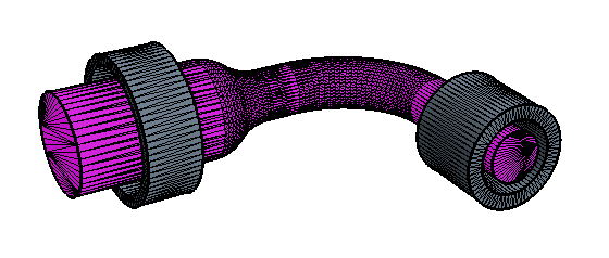
If you select more than one set of manifold faces, the total volume is calculated.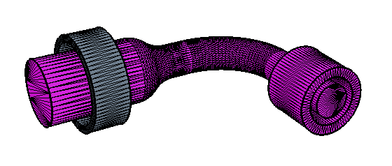
If you select a set of faces that are not manifold, as shown in the following example, an error message is displayed in the Output window.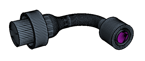
You can include contact faces in the selection; however, if you want to calculate the volume of two bodies that have a contact between them, do not include these faces in your selection.
You can calculate the volume where one body is encased inside another body. In this situation, the reported volume is the difference between the two bodies. If the two bodies are intersecting, subtract, intersect, or unite them before using this tool.
Mixed Query Tools
Mixed query diagnostics provide information specific to the combination of entities that are selected in the Graphics window.
 Distance Between Selected Vertex and Edges
- This query finds which of the selected edges is closest to the selected vertex and reports the shortest distance between them. It also reports the closest edge ID, the vertex ID and location, and the maximum distance from the vertex to the edges in the x-, y-, and z-direction, relative to the laboratory coordinate system. This query becomes available when you select only one vertex and at least one edge.
An example report is provided below:
Vertex-Edge Distance Report (m)
 Shortest distance = 0.0143231
 Source Vertex 21672 : [-0.138287 0.0417277 -0.0405851]
 Closest Edge 3857
 dx = 0.00102346
 dy = -0.014132
 dz = 0.00209533
Distance Between Selected Vertex and Faces
- This query finds which of the selected faces is closest to the selected vertex and reports the shortest distance between them. It also reports the closest face ID, the vertex ID and location, and the maximum distance from the vertex to the faces in the x-, y-, and z-direction, relative to the laboratory coordinate system. The shortest distance is measured between the vertex and the closest point on the closest face (that is, not necessarily the closest vertex). Select only one vertex and at least one face before this query becomes available.
An example report is provided below:
Vertex-Face Distance Report (m)
 Shortest distance = 0.0471872
 Source Vertex 15183 : [-0.0196444 0.0310554 0.0333477]
 Closest Face 3774
 dx = -0.0406806
 dy = 0.00704464
 dz = -0.0228494
Distance Between Selected Edge and Faces
- This query finds which of the selected faces is closest to the selected edge and reports the shortest distance between them. It also reports the closest face ID, the closest edge vertex ID and location, and the maximum distance from the edge to the faces in the x-, y-, and z-direction, relative to the laboratory coordinate system. The shortest distance is measured between the closest vertex on the edge and the closest point on the closest face (that is, not necessarily the closest face vertex). Select only one edge and at least one face before this query becomes available.
An example report is provided below:
Edge-Face Distance Report (m)
 Shortes distance = 0.127133
 Source Edge Vertex 7857 : [-0.15575 0.0320246 -0.127]
 Closest Face 60911
 dx = 0.097494
 dy = 2.20414e-006
 dz = 0.0815947
Geometric Range of Selected Faces/Edges/Vertices
- This query reports the minimum and maximum coordinate values (relative to the laboratory coordinate system) of a bounding-box that contains all selected faces, edges, and vertices. It also reports the dimensions (change in coordinate value) of the bounding-box in the x-, y-, and z-direction. To make this query available, make one of the following selections:
- At least one face and at least one vertex
- At least one face and at least one edge
- At least one vertex and at least one edge
An example report is provided below:Mixed Entity Geometric Range Report (m) Min. Global Value : [-0.148336 -0.03175 -0.0827226] Max. Global Value : [0.1905 0.139436 0.0348818] Components : dx = 0.338836 dy = 0.171186 dz = 0.117604You can view the geometric range using local coordinate systems.
To select a local coordinate system, click
 (Save-Restore-Select Views) and select
. Cylindrical coordinate systems only report radial and axial ranges; angular ranges are not reported. Spherical coordinate systems only report radial ranges.
 Find Leak Path
- This tool selects faces using the shortest path between one source and multiple target faces. See Using the Leak Path Mode.
 Tolerance from the Selected Faces to Neighboring Parts
- This query identifies neighboring parts that are within a given distance of a specified part face. The neighboring parts can be a set distance away, touching, or intersecting the specified face. This tool is available when you select at least one face. The selection must not span multiple parts.
When you run the query, a report is generated and lists the neighboring parts in alphabetical order. The closest distance of the neighboring parts to the selected part are also displayed:
Part Tolerance Report (m)
 Input part: Differential 1
 Search distance: 0.001
Found 8 parts within search distance:
 Part: Break 20 Closest distance: 0
 Part: Break 22 Closest distance: 0
 Part: Break 30 Closest distance: 0
 Part: Differential 1 Closest distance: 0.000785971
 Part: Steering Oil Tank Closest distance: 0
 Part: Transmission Rod Closest distance: 4.29961e-06
You can also choose to select the parts and faces that fall within the search distance that you set. This feature is useful for post-processing or inspecting geometry, such as when preparing to create a multi-part contact.
The original selection set can include contacts for the part and can also be a subset of the part. You do not need to select all the faces, so a single part surface can be selected, if preferable, and the output will only reflect results that are within the same tolerance as the original selection.
Query Part Tolerance Options
Click to the right of the Query Part Tolerance tool to display the options:
- Search Distance
- Specifies the maximum distance from the selected surface within which to search for neighboring parts. Parts that are within this search distance are found and reported in the Output window. If the Update Selection option is activated, the neighboring parts/surfaces are added to the selection set.
- Update Selection
- When activated, this option selects the parts/faces that are within the search distance. This option is activated by default. The option you choose in the
Selection Options group box controls what is selected.
Select parts selects the entire part that contains a face that falls within the search distance.

Select in-tolerance faces selects only the faces that fall within the search distance. The parts or faces are added to the existing selection set, in addition to the original faces that you originally select.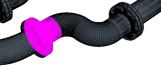
Deactivate the Select in-tolerance faces option to display the results of the query in the Output window, without selecting any parts or faces.