Turbomachinery Mesh Workflow
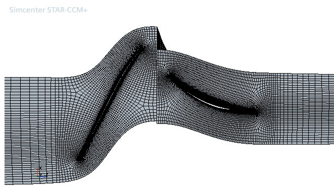
In Simcenter STAR-CCM+, you can generate a structured mesh for axial blade geometries using the Turbomachinery Mesh operation. Within this operation node, you can set the parameters that define the mesh properties along the blade, and in the spanwise and pitchwise directions.
- Provide the geometry for the simulation.You can create the geometry in 3D-CAD or import external geometry as parts. Make sure that the geometry meets the following requirements:
- The geometry can include a tip clearance between the blade and the hub or shroud.
- Fillets less than 0.1 mm will be ignored. Fillets larger than the regular O grid may compromise the mesh quality.
- Fillets are allowed at the hub and shroud and are detected automatically. To better resolve fillets, you are recommended to add at least 7 spanwise intervals per fillet.
- The geometry must not contain any bypass systems, squealer tips, or secondary cooling systems.
- The geometry must be an axial blade. The Turbomachinery Mesh operation only supports this type of geometry.
- The mesh operation benefits from parts containing an underlying CAD model, often with a better mesh being constructed as a result.
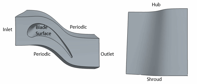
- Within the blade geometry, define all the domain and blade surfaces that are required by the Turbomachinery Mesh operation.These surfaces include the inlet, outlet, hub, shroud, blade surface, and if required, a blade tip surface.
 The blade surface:
- Can be a single surface or multiple surfaces. The optimal blade definition consists of two surfaces (or patches)—one for the pressure side and another for the suction side of the blade.
- Must not contain any sharp trailing edges or other sharp features, which are not compatible with the Turbomachinery Mesh operation. After you have removed any sharp features from the blade geometry, you can regenerate the mesh.
- If you create the model in 3D-CAD, create geometry parts.
- Assign parts to regions.
The initial surface tessellation must be of appropriate size and quality. A poor quality tessellation can lead to defects in the mesh such as folded or semi-folded faces. To make sure that the input surface mesh is of good quality, you can remesh the initial surface using the Surface Remesher before executing the Turbomachinery Mesh operation.
To remesh the surfaces:
- Create an Automated Mesh operation for the turbomachinery parts. Select the Surface Remesher and adjust the settings as follows and set everything else to default:
Property Setting Pre-part Meshing Activated Mesher Execution Mode Concurrent Base Size Set to 10% of the chord Target Surface Set to 50% of the base Minimum Surface Size You can estimate the Minimum Surface Size as: Where is the minimum radius of the blade profile, which is typically located at the trailing edge. You can measure directly using the measuring tool (see Using the Measurement Tool).
- Right-click the node and select .
The fillet surfaces should not be part of the hub or shroud surfaces. You should always combine them with the blade surfaces (SS) instead.
- Select the node and specify the relevant parts and part surfaces within the Properties window.The mesher treats any surface that is not assigned to these properties as periodic.
- Define the mesh structure:
- If required, create and define a custom Part Control:
- Right-click the node and select New.
- Select the node and specify the required properties.
You are recommended to use Custom Control to increase spanwise intervals for parts with tip gap features because tip layers reduce the number of blade layers. This requires only one custom control containing all the parts with tip gap.- Within the node select the required custom mesh controls.
- Within the Values node, specify the relevant values.
For more information on the custom controls, see Custom Control Properties. - Right-click the Turbomachinery Mesh node and select Execute.The operation results in a block structured hexahedral mesh in the flow passage around the blade. When you execute the mesh, the periodic surfaces float to allow for optimal mesh quality. This results in periodic surfaces which do not conform to the original geometry description.

This operation allows for serial or concurrent execution only. If you attempt to run the operation in parallel, the operation is forced to run in serial. Therefore, selecting the parallel mode does not speed up the execution.