Turbomachinery Mesh Properties Reference
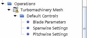
You define the blade, spanwise, and pitchwise parameters by setting the Properties available within each node for the Turbomachinery Mesh operation node.

Turbomachinery Mesh Properties
- Input Parts
- Specifies the geometry parts that represent the axial blade geometry and that provide the input for the turbomachinery mesh operation.
- Inlet Surfaces
- Defines the inlet surfaces of the domain.
- Outlet Surfaces
- Defines the outlet surfaces of the domain.
- Hub Surfaces
- Defines the hub surfaces. Must not include fillet part surfaces.
- Shroud Surfaces
- Defines the Shroud surfaces. Must not include fillet part surfaces.
- Blade Surfaces
- Defines the blade surfaces. Define separate part surfaces for the suction and pressure surfaces of the blade.
- Blade Tip Surfaces
- Defines the surfaces of the blade tip or hub. Set this property when the geometry contains a tip clearance near the hub or shroud. If none of the input parts has tip clearance (that is, the blade spans from the hub to the shroud), you can leave this property blank.
Blade Parameters Properties
- Near Wall Thickness
- Defines the absolute value for the thickness of the first layer of cells along the blade surface.
- Number of Intervals
- Defines the number of divisions for the mesh along the blade profile.
- Blade Tip Mesh
- Allow you to specify the type of mesh used for the blade tip surface. There are two options:
- Quadrilateral
- Triangular
Spanwise Settings Properties
- Number of Intervals from Hub to Shroud
- Defines the number of divisions for the mesh in the spanwise direction (between the hub and shroud).
- Number of Intervals In Tip Gap
- Defines the number of divisions for the mesh between the blade tip and the hub or shroud surface. The number of intervals must be less that the number of intervals between the hub and shroud. The number of intervals in Tip Gap is included in the total number of intervals from Hub to Shroud. This property is available only when you specify blade tip surfaces (see Blade Tip Surfaces)
- Hub Near Wall Thickness
- Defines the absolute value for the thickness of the first layer of cells at the hub surface in the spanwise direction.
- Shroud Near Wall Thickness
- Defines the absolute value for the thickness of the first layer of cells at the shroud surface in the spanwise direction.
Pitchwise Settings Properties
- Distribution Method
- Allows you to specify how the mesh cells are distributed in the pitchwise direction. There are 2 options:
- Number of Intervals—defines the number of divisions in the pitchwise direction. If you select this method Simcenter STAR-CCM+ calculates the growth rate that satisfies the specified number of intervals.
- Growth Rate—defines the ratio between the thicknesses of consecutive cell layers in the pitchwise direction near the blade. If you select this method, Simcenter STAR-CCM+ calculates the number of intervals using the Near Wall Thickness defined within the Blade Parameters.
- Number of Intervals
- Defines the number of divisions in the pitchwise direction. For more information, see Distribution Method.
- Growth Rate
- Defines the ratio between the cell thicknesses of successive layers within the mesh in the pitchwise direction near the blade. For more information, see Distribution Method.