Performing Nonlinear Normal Modes Analysis
The Solid Stress Normal Modes solver also supports nonlinear setups. To see the effect of nonlinearities on the normal modes of the structure, define the turbine blade in a rotating reference frame and recalculate the normal modes.
- Right-click the and select .
- Select the node and set Rotation Rate to 30.0 rpm.
- Multi-select both the and the nodes, and set the Reference Frame to Rotating.
- Right-click the node and select Select Models...
- In the Optional Models group box select the Nonlinear Geometry model.
- Select the node.
- Deselect the Linear Strain (Small Strain) model.
- Select the Green-Lagrange (Small Strain) model. Click Close.
- Select .
-
Click
 (Run).
- Once the simulation is complete, right-click the node and select Perform Normal Modes Analysis.
-
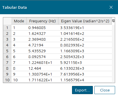
To view the results, right-click and select Tabulate.

The results show that with the introduction of a rotating reference frame and the Nonlinear Geometry model the normal modes have changed from the linear simulation. For example, the seventh normal mode has increased. This change in results for the nonlinear simulation is due to the normal modes solver accounting for the nonlinear effects of the rotation such as centrifugal force and the variations in stiffness of the geometry. In contrast, the linear simulation only considers the initial configuration and stiffness.
- Save the simulation.