Generating the Hexahedral Mesh
In this tutorial, you mesh the beam with 3D solid hexahedral elements using the Simcenter STAR-CCM+ Directed Mesher.
By default, hexahedral elements are generated with 8 nodes (hex8), but you can add mid-side nodes to use hexahedral elements with 20 nodes (hex20).
- Right-click the node and select .
- In the Create Directed Mesh Operation dialog, select Beam from the Parts list then click OK.
- Right-click the node and select Edit...
-
In the
Directed Mesh panel, set the following properties to specify the source and target surfaces for the directed mesh operation:
Node Property Setting Source Surfaces Source Surfaces wall side - lower flange wall side - upper flange wall side - web Target Surfaces Target Surfaces free side - lower flange free side - upper flange free side - web
To create a patch mesh on the beam
surface at the wall, you are going to define the following patch topology:
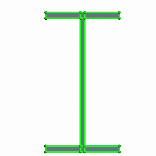

Start by adding a new source mesh:
- In the Directed Mesh panel, right-click Source Meshes and select .
- In the Part Collection For This Source Mesh dialog, select Beam from the Connected Parts list then click OK.
- Click anywhere in the Directed Mesh 1 scene and press the <T> key to adjust the view.
-
In the in-place
Edit dialog, click
 (Auto-populate feature edges with patch curves).
Split the surface of each flange into three patches:
- In the Directed Mesh 1 scene, zoom in to focus on the upper flange.
-
Click
 (Split the selected patch curve) and maintain the split patch curve option,
At Picked Location.
-
Click the external feature edge of the flange in two different locations, as shown below:
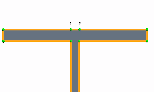
- Press <Esc> to exit the split patch curve mode.
Adjust the coordinates of the new vertices as follows:
- Click the vertex that is marked as 1 in the image above.
- In the Patch Vertex Location Options group box, set the X coordinate to -0.0028 and click Apply.
- In a similar way, set the X coordinate of vertex 2 to 0.0028.
-
Click
 (Create Patch Curve) then click the vertices 2, 3, 4 and 1 in order, as shown below:
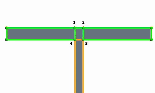
-
Following the same procedure, split the lower flange surface into three patches.
The patch topology is now complete and looks as shown at the beginning of this section.
Complete the patch mesh by specifying the number of divisions within the patch curves:
- In the Edit in-place dialog, switch the Mode to Patch Mesh.
-
In the
Directed Mesh 1 scene, multi-select the following patch curves:
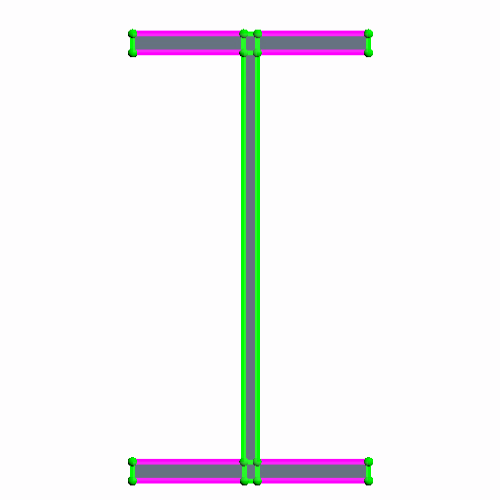
- Set Number of Divisions to 7 then click Apply.
-
Multi-select the following patch curves:
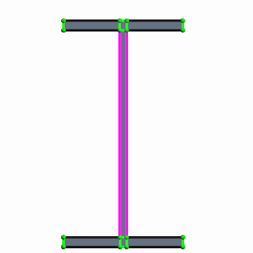
- Set Number of Divisions to 19 then click Apply.
-
For all the remaining patch curves, set
Number of Divisions to
1.
The final patch mesh looks as shown below:
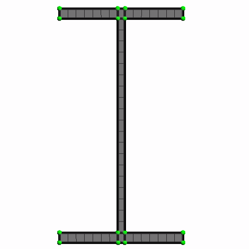
You are now ready to generate the volume hexahedral mesh.
- Close the Edit in-place dialog.
- Select the node and set Number of Layers to 70.
- Click Close Directed Mesh.
-
In the simulation tree, right-click the
node and select
Execute.
When the mesh generation is complete, you can visualize the mesh with a method of your choice, such as creating a mesh scene.
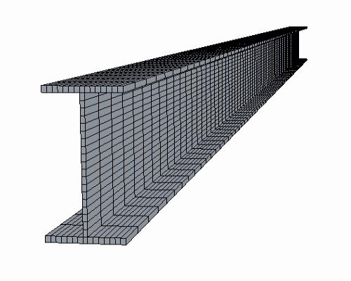
To add mid-side nodes:
- Expand the node.
-
Select the
Mid-side Vertex Option and set
Mid-side Vertex to
Add - Linear Interpolation.
The mid-side nodes are added when you run the simulation.
- Save the simulation.