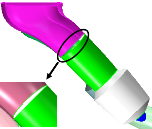
Use the tools in 3D-CAD to clean and prepare the exhaust pipe for
simulation. These preparations include filling the end holes and closing up a gap.
-
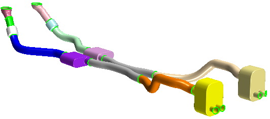
In the toolbar at the top of the 3D-CAD View scene, change
 (Color
Mode) to
  (Distinguish
Bodies).
Before repairing the geometry, check the validity of the parts.
To run a validity check:
-
Right-click the Exhaust Pipe node and select
 (Check Validity).
A message with the results of the validity check is printed
in the
Output window. In this case, the
following message is displayed:
All bodies of model are valid.
-
Use the Fill Surface operation to close the inlets and outlets:
-
In the Graphics window, select the
edges that surround the first inlet.
You can double-click a single free edge to automatically
select all the free edges connected to it.
-
Right-click one of the edges and select Fill
Surface.
The Fill Surface
panel appears on the left of the Graphics window.
-
In the Fill Surface panel, click
OK.
The inlet hole is filled with a surface.
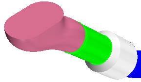
-
Repeat the steps above to fill the second inlet.
-
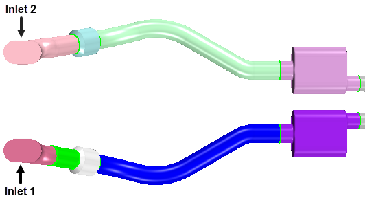
Following the labels in the image below, rename the inlet faces to
Inlet 1 and Inlet 2,
respectively.
-
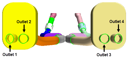
Repeat the same process to fill the holes of the outlets. Rename the
outlet faces to Outlet 1, Outlet
2, Outlet 3 and Outlet
4, according to the image below.
Use the Search tool to carry out a search on the entire
geometry to find bodies that are interfering with one another.
-
To search for bodies that are intersecting:
-
Click
 (Show Filter) on the right side of the 3D-CAD View scene.
-
Set Selection Mode to
 (Entire CAD model).
-
Set Input Type to
 (Bodies).
-
In the Search Criteria group box,
create the following query:
- Select the Conditions option.
- Choose Clash + Body Pair + is +
Interference. Click
 (Commit Changes).
-
Click Search.
The clashing bodies are displayed in the graphics window.
-
Display the results in a table to identify which bodies are clashing:
- In the Results
panel, next to Create, select
Table and click
OK.
By default,
the result table appears between the 3D-CAD simulation tree
and
3D-CAD View scene.

- Close the table and, in the Design Filter 1: Input window, click
Cancel.
-
In the Vis toolbar, click
 (Save-Restore-Select Views) and select .
-
If you zoom closely on Inlet 1, you can see that
there is a gap between Body 1 and Body
3.
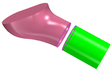
For this tutorial, you close the gap using the Bridge Surface
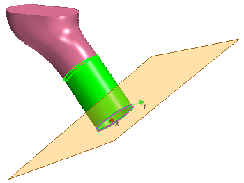
tool. Because part of the surface of Body 1 intersects with
Body 3, you must make planar cuts across Body
1 and Body 3. These cuts remove the
overlapping surfaces and provides the Bridge Surface tool with uniform edges from
which to grow the surface.
-
To isolate the parts for repair, under the Body Groups
node, multi-select Body 1 and Body
3, right-click and select Show Only.
-
To slice Body 1:
-
Right-click the edge of Body 1 (the short
section of straight pipe) furthest from Body 3
and select .
-
In the Plane from Curve panel, set
Type to Fitting Plane
and click OK.
-
In the feature tree, right-click Plane 1 and
select .
-
In the Plane by Transformation panel,
enter -0.095 for the Z
component of the Translation Vector and click
OK.
-
Expand the Body Groups node, right-click
Body 1, and select .
-
In the Slice panel, set the following
parameters:
| Parameter |
Setting |
| Keep Side
|
Front Side
|
| Cutting Tools
|
Plane 2
|
-
Click OK.
-
To slice Body 3:
-
In the feature tree, right-click Plane 2 and
select .
-
In the Plane by Transformation panel,
enter -0.0150 for the Z
component of the Translation Vector and click
OK.
-
Expand the Body Groups node, right-click
Body 3 and select .
-
In the Slice panel, set the following
parameters:
| Parameter |
Setting |
| Keep Side |
Back Side |
| Cutting Tools |
Plane 3 |
-
Click OK.
-
To close the gap:
-
In the feature tree, multi-select Plane 1,
Plane 2 and Plane 3.
-
Right-click on the selection and select
Hide.
-
In the graphics window, multi-select the free edges on either side of
the gap between Body 1 and Body
3.
-
Right-click on the selection and select Bridge
Surface.
-
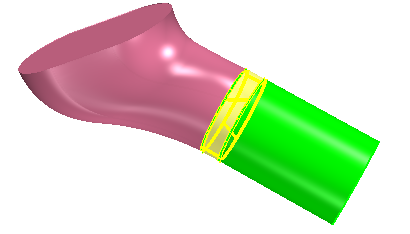
In the Bridge Surface panel, activate the
following options:
| Bridge Surface Options |
| Tangent to Faces for Source
Edges |
| Tangent to Faces for Target Edges
|
| Sew Bodies |
A preview of the operation is displayed in the
3D-CAD
View scene.
-
Click OK.
-
Right-click a blank space in the 3D-CAD View scene and
select .
The geometry is now ready and you can exit 3D-CAD.
-
Click the Close 3D-CAD button at the bottom of the
object tree.
| 注 | The 3D-CAD View scene is closed automatically upon exiting
3D-CAD. |
-
Save the simulation.
 (Color
Mode) to
  (Distinguish
Bodies).
 (Check Validity).
A message with the results of the validity check is printed in the Output window. In this case, the following message is displayed:


 (
( (
(

 (
(