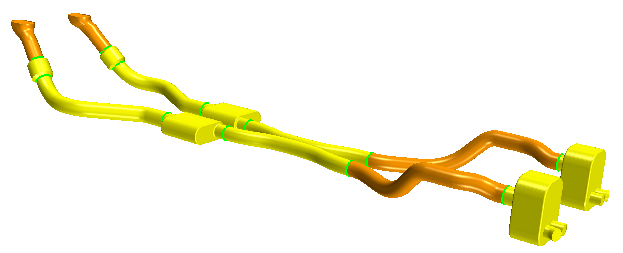
Parts-Based Shells: Exhaust Pipe
Simcenter STAR-CCM+ provides support for thin-walled structures that are best represented by a single-cell layer during simulation. These single-cell layers are known as shells. One of the main advantages of using shell elements is that it reduces the computational time and resources required for simulations.


After preparing the CAD mode, you create attached shell parts from the solid bodies of the exhaust pipe. When you generate the mesh, Simcenter STAR-CCM+ creates a single-cell layer for the shell parts.
As well as demonstrating the CAD preparation and volume meshing steps, this tutorial illustrates how to set up the necessary interfaces, physics models, and boundary conditions for running a CHT simulation with a thin-walled structure.