Wrapping the Surface and Detecting Contacts

Create two surface wrapper operations and set the properties that apply to the geometry parts on which they operate.
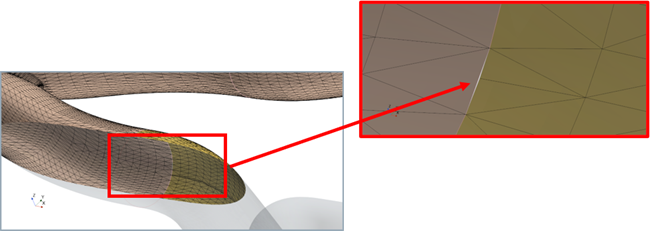
For this simulation, the surface wrapper operation is used to create the flow volumes (air and exhaust gas). Before creating the surface wrapper operation, use the Zip Edges operation to stitch all the attached shell parts together. The image below shows a gap that exists in the geometry between two attached shell parts.

  1. Create a Zip Edges operation for the attached shell parts:
    1. Right-click the Geometry > Operations node and select New > Surface Preparation > Zip Edges.
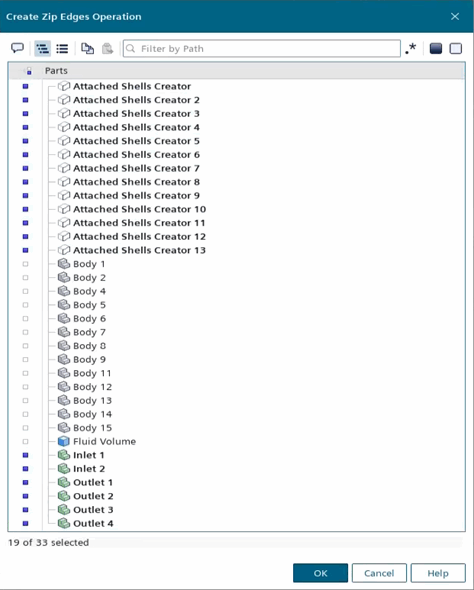
    2. In the Create Zip Edges Operation dialog, select the following parts and click OK:
      • All Attached Shells Creator parts
      • All Inlet and Outlet parts


    3. Select the Operations > Zip Edges node and set Zip Mode to New Description - Discrete (confirm selection).
      The Zip Edges operation only supports shell parts when you set Zip Mode to New Description - Discrete.
    4. Right-click the Geometry > Operations > Zip Edges node and select Execute.
  2. Set up a surface wrapper mesh operation for the fluid volume:
    1. Right-click the Geometry > Operations node and select New > Surface Preparation > Surface Wrapper.
    2. In the Create Surface Wrapper Auto Mesh Operation dialog, select the following parts and click OK:
      • All Attached Shells Creator parts
      • Fluid Volume
      • All Inlet and Outlet parts
    3. Rename the Surface Wrapper node to Surface Wrapper (All Parts).
    4. Select the Surface Wrapper (All Parts) node and activate the following properties:
      • Create Weak Contacts With Input Parts
      • Link Output Part Name (confirm selection)
    5. Select the Surface Wrapper (All Parts) > Default Controls > Base Size node and set Value to 0.025 m.
    6. Create and define a custom surface control that specifies a coarse mesh for the fluid volume:
      1. Right-click the Surface Wrapper (All Parts) > Custom Controls node and select New > Surface Control.
      2. Rename Surface Control to Surface Control (Fluid Volume).
      3. Select the Surface Control (Fluid Volume) node and click the custom editor for Part Surfaces.
      4. In the Surface Control (Fluid Volume) - Part Surfaces dialog, select Fluid Volume and click OK.
      5. Edit the Surface Control (Fluid Volume) node and set the custom control settings as shown below:
        Node Property Setting
        Controls
        Target Surface Size Target Surface Size Custom
        Minimum Surface Size Minimum Surface Size Custom
        Values
        Target Surface Size Size Type Relative to base
        Percentage of Base 200
        Minimum Surface Size Size Type Relative to base
        Percentage of Base 100
    7. Right-click the Geometry > Operations > Surface Wrapper (All Parts) node and select Execute.
  3. Set up a surface wrapper mesh operation for the exhaust pipe:
    1. Right-click the Geometry > Operations node and select New > Surface Preparation > Surface Wrapper.
    2. In the Create Surface Wrapper Auto Mesh Operation dialog, select all the following parts and click OK:
      • All Attached Shells Creator parts
      • All Inlet and Outlet parts
    3. Rename the Surface Wrapper node to Surface Wrapper (Exhaust).
    4. Select the Surface Wrapper (Exhaust) node and activate the following properties:
      • Create Weak Contacts With Input Parts
      • Link Output Part Name (confirm selection)
    5. Select the Surface Wrapper (Exhaust) > Default Controls > Base Size node and set Value to 0.02 m.
    6. Right-click the Geometry > Operations > Surface Wrapper (Exhaust) node and select Execute.
  4. Create a weak contact creator operation between the exhaust pipe and fluid volume:
    1. Right-click the Geometry > Operations node and select New > Surface Preparation > Contact Creator.
    2. In the Create Contact Creator Operation dialog, select Surface Wrapper (All Parts) and Surface Wrapper (Exhaust) and click OK.
    3. Right-click the Geometry > Operations node and select Execute.
  5. Save the simulation.