Creating Attached Shell Parts
To create shell parts form the exhaust pipe parts, you can use the Attached Shells Creator operation.
A shell part has two part surfaces—a front surface and a back surface. You can apply boundary conditions on the part surfaces respectively.
- Right-click the node and select New Geometry Part.
- In the Parts Creation Options dialog, click OK.
Some of the exhaust surfaces are used for flow boundary
conditions in the final simulation. These surfaces must be converted to regular
parts (rather than shell parts).
-
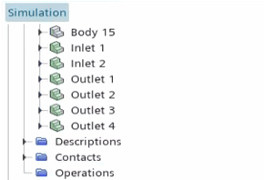
To separate the inlets and outlets into individual regular (solid) parts:
The solid bodies are listed in the node, as shown below.

To create the attached shell parts:
- Right-click the node and select .
-
In the Create Attached Shells Creator
Operation window set the following properties and click
OK:
Property Setting Input Parts All [Body] parts Part Surfaces All Surfaces Execute Operation Upon Creation Activated -
Right-click the Scenes node and select .
A new geometry scene, Geometry Scene 1, is added to the Scenes node. This scene automatically displays all parts that are listed under the node.
-
Create a part shape for the fluid volume:
-
Split the Fluid Volume surfaces so that boundaries can
be identified:
- Right-click the node and select Split by Angle.
- In the Split Part Surfaces by Angle dialog, click OK.
- Rename Block Surface 3 to Inlet and Block Surface 6 to Outlet.

- Save the simulation.