Fluid-Structure Interaction Reference
- FSI Coupling Specification
- Allows you to check the coupling between the
solid and fluid domains. This property is read-only and depends on the
motion settings for the solid region.
- For problems where the solid is Stationary or subject to rigid body or superposed rigid body motions, this property is set to Solid Motion.
- For problems where the solid is subject to Solid Displacement, this property is set to Solid Displacement.
- FSI Fluid Load Ramping
- Surface Load Linearization
- Available when the Nonlinear Geometry model is active in the solid physics continuum. See Nonlinear Geometry Model Reference.
Fluid Structure Coupling Solver
The fluid structure coupling solver manages the mapping of the coupled fields between the fluid and solid. Within the properties of the solver, you can specify the stabilization method across the solid-fluid interface.
- Solver Properties
-
- Stabilization Method
- Allows you to choose the method of stabilization for two-way coupled FSI simulations. As well as stabilizing the solution, the stabilization method accelerates the convergence of the coupled system. One-way coupled problems do not require stabilization.
- Model Compatibility
- Allows you to select whether the model
compatibility is enforced. The options for this are:
- Enforce—prevents the simulation from running
if the simulation contains any of the following
incompatible settings:
- Morph At Inner Iterations is deactivated.
- Boundary-mode fluid-structure interfaces.
- 2nd order temporal discretization with the Newmark or Generalized-α time integration method selected.
- Ignore—allows the simulation to run to completion when it contains incompatible settings. However, results may be inaccurate if this option is selected.
- Enforce—prevents the simulation from running
if the simulation contains any of the following
incompatible settings:
- Solver Controls
-
- Displacement Convergence Tolerance
-
- Convergence Tolerance —sets the tolerance by which to assess convergence of the coupled FSI solution. When the Solid Stress Displacement residual is less than the specified tolerance, the solid stress computation stops for the remainder of the time-step. The default value of 1E-10 is determined as the Multiplier times the Minimum Limit of the Displacement Criterion.
- Use Reference Minimum Value—when activated, the Convergence Tolerance is equal to the Minimum Value of the Displacement Criterion times the Multiplier. When deactivated, you specify the tolerance directly using the Convergence Tolerance property. Specifying a value for the Convergence Tolerance automatically deactivates Use Reference Minimum Value. You can activate Use Reference Minimum Value only when the Criterion Option of the Displacement Criterion is set to Minimum.
- Multiplier—the value of the multiplicative factor applied to the Minimum Value of the Displacement Criterion to determine the Convergence Tolerance. The default value is 1E-4. See 使用监视器作为停止条件.
- Constant Displacement Under-relaxation
- See Stabilization Methods.
Field Functions
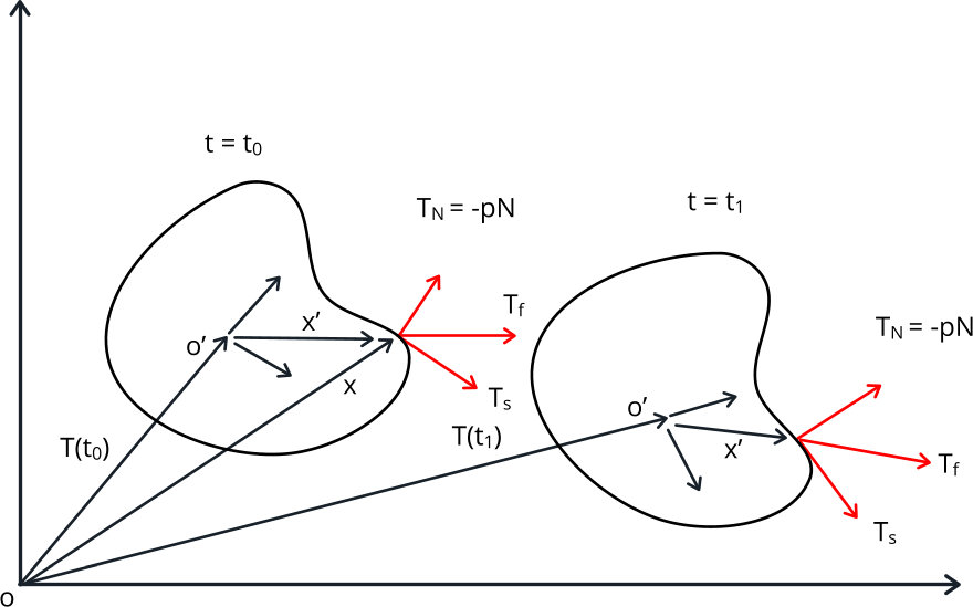
- FSI Traction
- Vector field function that represents the
fluid traction on the fluid side of the FSI interface. The FSI traction
is the sum of the shear force
and the pressure component in the normal
direction
after FSI Fluid Load Clipping and/or
Ramping have been applied such that:(343)
and
where is the fluid pressure on the interface and is the normal vector to the interface.If on the fluid side of the FSI interface changes in the laboratory coordinate system , Simcenter STAR-CCM+ calculates the pressure and shear component.
- Mapped FSI Traction
- Vector field function that represents the
fluid traction mapped onto the solid side of the FSI interface.
The mapped FSI traction is stored as the combination of and and represents a load that follows the motion of the solid, for example, from time to time .

- Mapped FSI Traction (pressure component)
- Scalar field function which represents the pressure component of the Mapped FSI Traction on the solid side of the FSI interface. Only available if Temporary Storage Retained is activated under the Fluid Structure Coupling solver.
- Mapped FSI Traction (shear component)
- Vector field function which represents the shear component of the Mapped FSI Traction on the solid side of the FSI interface. Only available if Temporary Storage Retained is activated under the Fluid Structure Coupling solver.