Modeling Electrochemical Surface Reactions

Simcenter STAR-CCM+ allows you to model electrochemical reactions on boundary surfaces around the physics continuum for the fluid, on the interface surfaces between a solid continuum and the fluid, and on unresolved surfaces inside of porous media. In all of these cases, except in fluid films, you can choose to model the production and consumption of electrochemical species from reactions—or you can choose to model the production and consumption of charged species from reactions on boundaries and in porous regions.

Follow this procedure to model electrochemical surface reactions.

Refer to Electrochemical Species Model Reference and Electrochemical Reaction Model Reference.

For improved convergence, use a double precision version of Simcenter STAR-CCM+.
To simulate electrochemical surface reactions, some applications require that you define several solid and fluid continua. Make sure that you select the necessary models for continua on both sides of the reactive interface.

  1. Set up the fluid physics continua.
    1. For physics continua that represent a fluid, select the following models, with Auto-Select recommended models activated:
      Group Box Model
      Space Select one
      Time Select one
      Material Either:
      • Single phase flows:
        • Multi-component Gas or Multi-component Liquid (only if you intend to use the Charged Species Effects model or the Concentrated Electrolyte model—not the Electrochemical Species model).
        • Liquid
        • Gas
      • Multiphase flows:
        • Multiphase model is required if you want to account for phase volume fraction s in electrochemical reactions.
      Reaction Regime

      (available when Multi-Component Gas is selected)

      Non-Reacting
      Flow

      (available for single phase flows)

      Segregated Flow
      Multiphase Model

      (available for multiphase flows—when Multiphase is selected)

      Select one:

      In order to specify reactant and product species from a phase in an electrochemical reaction mechanism, Multiphase Mixture (MMP) or the Eulerian Multiphase ( EMP) model is required. Otherwise, only secondary current distribution reaction formulation is possible. See Reaction Formulation and Current Distribution Methodology.

      • Volume of Fluid (VOF): Provides energy models which calculate temperature for the combined mixture of phases.
      • Multiphase Mixture (MMP): Provides energy models which calculate temperature for the combined mixture of phases.
      • Eulerian Multiphase (EMP): Provides the Phase Coupled Energy model which solves for temperature per phase.
      Equation of State

      (available for single phase flows)

      Select one

      (Constant Density is the most appropriate choice for liquids with very small temperature changes. Also required if you intend to specify initial conditions and/or boundary conditions for species in units of molar concentration.)

      Viscous Regime Select one
      Optional Models Electrochemistry

      Concentrated Electrolyte

      Electrochemistry

      Electrochemical Reactions

      Electromagnetism

      Electrodynamic Potential

    2. If required, you can include electrochemical species or charged species in the reaction mechanism (but not both at the same time).
      • To include electrochemical species in the electrochemical surface reaction mechanisms (required for sorption reactions), select the Electrochemical Species model from the Optional Models group box. The Electrochemical Species model is not available when the Multiphase model, Multi-Component Gas model, or Multi-Component Liquid model is selected.

        See Electrochemical Species Model Reference.

      • To include charged species in the electrochemical surface reaction mechanisms, select the Charged Species Effects model from the Optional Models group box. The Charged Species Effects model is not available when the Porous Media model is selected—however, you can use porous regions instead.

        See Charged Species Effects Model Reference.

      • To include concentrated electrochemical species, select the Concentrated Electrolyte model from the Optional Models group box.

        See Concentrated Electrolyte Model Reference.

    3. Select any extra Optional Models that you require for the fluid physics continuum.
      • Porous Media—to model electrochemical surface reactions which involve solid porous phases.

        See Porous Media Models.

      • Select an energy model.

        Segregated Fluid Isothermal—to set a constant temperature without solving an additional transport equation.

        If no temperature model is selected and the Electrochemical Species model is selected, the Electrochemical Species model runs with a constant temperature of 293.15K.
      • Select a heating model.

        Electrochemical Reaction Heating (and an Energy model) for all continua which interface a reactive surface—to model heat contributions that are due to electrochemical reactions at interfaces.

        See Electrochemical Reaction Heating Model Reference.

        Ohmic Heating—to model heat release due to ion transport in bulk phases and due to resistances at reacting surfaces. You can also select the model for all ionically conductive domains.

        See Ohmic Heating Model Reference.

        Make sure that you select heating and energy models for all physics continua which are next to a reactive interface.
      • Fluid Film—to model secondary current distributions due to electrochemical reactions within a fluid film.

        See Modeling Fluid Film.

    4. Click Close.
  2. If the Gradients and Electrochemical Species models are both selected and any electrochemical species are in low concentration, select the Models > Gradients node and set Limiter Method to MinMod.
When simulating fluid domains in which the diffusion at the flow boundaries is high, and not imperative to include in the calculations, you can choose to neglect this diffusion and only account for the diffusion of species within the domain. This feature is useful when reviewing the mass conservation of fuel cells.
  1. To neglect diffusion at flow boundaries, within the fluid continuum, multi-select all segregated flow, species, and energy models and deactivate Flow Boundary Diffusion.
  2. If the simulation includes a solid on which surface reactions take place, add a physics continuum for this solid.
    1. Select the following models (with Auto-Select recommended models activated):
      Group Box Model
      Space Select one
      Time Select one
      Material Solid
      Optional Models Electrochemistry
      Enabled Models

      Electrochemical Reactions (selected automatically)

      Electromagnetism (selected automatically)

      Gradients (selected automatically)

      Electrodynamic Potential (selected automatically)

    2. Select any extra Optional Models that you require for the solid physics continuum.
      For example
      • Solid Ion—when modeling electrochemical reactions in a coincident fluid or porous continuum (using the Porous Media model) which include ions from this solid continuum, such as in Solid Oxide Fuel Cells (SOFCs).
      • An energy model.
      • Electrochemical Reaction Heating—to model heat contributions that are due to electrochemical reactions at interfaces.
      • Ohmic Heating—to model heat release due to ion transport in bulk phases and due to resistances at reacting surfaces.
    3. Click Close.
  3. If you are using the Multiphase model, set up the phases and define any phase interactions. See Defining Eulerian Phases and Defining Phase Interactions.
    For Eulerian phases which participate in reactions, select the Multi-Component Liquid or Multi-Component Gas model.
  4. If you have a solid continuum present in the simulation, you can optionally choose to solve for the electric potential within the solid material. Otherwise, set a constant electric potential value on the surface that bounds the fluid:
    • To set a constant electric potential on the fluid bounding surface:
      1. Expand the Regions > [Fluid Region] > Boundaries > [Boundary] node.
      2. Select the Physics Conditions > Electrochemistry Mechanism Option node and set Mechanism to [Electrochemical Mechanism].
      3. Select the [Boundary] > Physics Values > Electrode Electric Potential node and specify the electrode electric potential value.
    • To account for the electric potential variation within the fluid and the solid at a reacting interface, select the Interfaces > [Interface] > Physics Conditions > Electrochemistry Mechanism Option node and set Mechanism to [Electrochemical Mechanism].
      In contrast to using an electrochemical surface mechanism at boundaries, there is no option to set the Electrode Electric Potential within the interface physics values. The Electric Potential value for the electrode is obtained internally from the solid.
When modeling electrochemical surface reactions without defining electrochemical species—such as in fluid films, you can choose to account for electrical resistance.

This feature is also useful when modeling some applications in which electrochemical species are defined, such as catalyst resistance in fuel cells, corrosion products or organic tissues at interfaces, and SEI interfaces in batteries.

  1. To account for electrical resistance, do one of the following:
    • When an electrochemical surface mechanism is set on the interface, specify the electrical resistance at the interface. Select the Interfaces > [fluid/solid interface] > Physics Values > Electrical Resistance node and specify the electrical resistance. When more than one fluid region contacts the solid region, you can specify the electrical resistance at each boundary or interface independently. This option is not available for baffle interfaces between porous phases when using the Electrodynamic Potential model.
    • When an electrochemical surface mechanism is set on the boundary, specify the electrical resistance at the boundary. Select the [boundary] > Physics Values > Electrical Resistance node and specify the electrical resistance.
    • When an electrochemical surface mechanism is set on the region, specify the electrochemical resistance at the region. Select the Region > Physics Values > Electrochemical Resistance node and specify the electrical resistance.
When modeling electrochemical surface reactions at baffle interfaces between porous phases when using the Electrodynamic Potential model, you can choose to account for transverse thermal resistance at the interface.

This feature is useful when using phasic porous media to simulate reactive catalyst layers in fuel cells.

  1. To account for thermal resistance:
    1. Select the Interfaces > [baffle interface] > Physics Conditions > Baffle Thermal Option node and set Baffle Thermal Option to Conducting.
    2. Select the Interfaces > [baffle interface] > Physics Values > Thermal Resistance node and specify the thermal resistance.
  2. If the simulation uses the Porous Media model to resolve electrochemical reactions on geometrically unresolved surfaces, set up the porous phases.
    1. For reactions in a 3D region, in each of the fluid continua which use the Porous Media model, create the required phases—right-click the Porous Media > Porous Phases node and select New.
      Conductor or binder (batteries and fuel cells) At least one phase is required for the transport of electrons—which must use the Electrodynamic Potential model.
      Active material (batteries) At least one phase is required for each active electrode material—which must use the Sub-grid Particle Intercalation model.
      Electrolyte (batteries) or electrolyte membrane (fuel cells) At least one phase (or continuum) for the transport of ions—which must use both the Electrodynamic Potential model, and the Solid Ion model.
    2. For reactions at a 2D interface, in each of the fluid continua which use the Porous Media model, right-click the Porous Media > Porous Phases node and select New.
      Conductor or binder (batteries and fuel cells) Only one phase is required for the transport of electrons—which must use the Electrodynamic Potential model.
      Electrolyte (batteries) or electrolyte membrane (fuel cells) A new phase for the electrolyte is not required—the solid physics continuum on the other side of the interface represents the electrolyte.
    3. Right-click the Porous Phases > [Porous Phase] node and select Select Models. Then select the required models.
    4. The Electrodynamic Potential model provides the Electrical Conductivity material property. Select one of the available options. See Electrical Conductivity.
    5. The Sub-grid Particle Intercalation model provides the Elemental Composition and Particle Radius material properties. Additionally, this model provides the Maximum Concentration and Molecular Diffusivity material properties, which are properties of the ion diffusing into the vacant space within the solid porous phase. See Material Properties.
When defining electrochemical surface reactions, you can include gas or liquid components and electrochemical species components in the same reaction. Before defining the reactions, you specify the segregated material species and electrochemical species that are present in each continuum.
  1. Define the material species.
  2. If the Electrochemical Species model is selected, create the solid species that represent the solid surface in the electrochemical surface reactions:
    1. Expand the Electrochemical Reactions > Surface Mechanism Manager > [Electrochemical Mechanism] node.
    2. Right-click the Reacting Surface > Solid Mixture > Solid Species node and select Select Mixture Components.
    3. Select all of the solid species that represent the solid surface in the electrochemical surface reactions. If you cannot find a solid species component, you can select a similar solid species component and modify its material properties to change the type and quantity of atoms.
    4. Click Apply, then Close.
    If you did not select the Electrochemical Species model, the solid material properties are taken from the solid physics continuum.
If you selected the Electrochemical Species model, specify the electrochemical reaction species components and the method for solving the concentrations of the electrochemical species.
  1. To modify the Electrochemical Species model, do the following:
    1. Right-click the Electrochemical Species > Electrochemical Species Components node and select Select Mixture Components.
    2. Select all of the electrochemical species that represent the reactants and products in the electrochemical surface reactions. If you cannot find a complex electrochemical species component, you can either:
      • Close the dialog, add electrochemical species to the database, then reopen the Select Mixture Components dialog, and select the species. See Modifying a Copy of the Material Database.
      • Select a similar electrochemical species component and modify its material properties to change the charge, and the type and quantity of atoms.
    3. Click Apply, then Close.
    4. To modify the composition or properties of an electrochemical species component, expand the Electrochemical Species Components > [Electrochemical Species Component] node and edit the Material Properties as required. See Electrochemical Species Component Reference.
    5. Select the Electrochemical Species node and specify the Electrochemical Species Solver Option as Coupled or Segregated.
      The Coupled Electrochemical Species Solver provides the best stability and is more capable of reaching convergence at high current densities than the Segregated Electrochemical Species Solver. However, the Segregated Electrochemical Species Solver runs faster at low current densities.
If you selected the Solid Ion model, specify the electrochemical species components in the solid continuum which participate in the electrochemical reactions.
  1. To specify the solid ion electrochemical species components, in the solid continuum, right-click the Solid Ion > Electrochemical Species Components node and select Select Mixture Components. You can add and amend species in the same way as described above for the Electrochemical Species model.
If you use the Electrochemical Species model with the Electrodynamics Potential model, you adjust the electrical conductivity.
  1. Expand the Models > [Material] > Material Properties node, select the Electrical Conductivity node, and set Method to Electrochemical Species.
Create the electrochemical surface reaction mechanisms. When using the electrochemical reactions model with the Multiphase model the model behaves as non-phasic, which means that there is not an electrochemical reaction mechanism or electric potential per phase, but for the "mixture" of phases.
When specifying the reactants and products, make sure that:
  • There are the same number of each type of atom in the reactants and products—in any reaction, matter cannot be created or destroyed.
  • The overall charge from the reactants and products must balance so that the total electric charge that is created in each reaction is zero.
  • Electrons are specified as reactants or products—in electrochemical reactions, electrons must be produced or consumed to generate an electric current.
  1. Expand the Continua > Physics 1 > Models > Electrochemical Reactions node then right-click the Surface Mechanism Manager node and select New Surface Mechanism.
  2. If you want to account for non-default phase volume fraction in sorption and electrochemistry reactions, select the Surface Mechanism Manager > [Electrochemical Mechanism] > Models > Reacting Surface node and activate Expert options. This option enables Phase Interaction Area Exponents where you can set reaction exponents, see Phase Interaction Area Exponents.
  3. Create the reactions and specify the reaction type for each reaction.
    1. Right-click the Surface Mechanism Manager > [Electrochemical Mechanism] > Reacting Surface > Reactions node and select New Reaction.
    2. For each reaction, select the Reacting Surface > Reactions > Reaction [n] node and set Type.
    See Type.
  4. Set the reaction properties such as equilibrium potential, reaction formulation, exchange current, and/or vacancy rate exponent (only available with the Sub-grid Particle Intercalation model). See, Reaction [n] Reference for a full list of available properties and set-up options.
Electrochemical reactions need an understanding of solid and electrolyte simulation domains in order to correctly apply the equilibrium electric potential jump at an interface. In Simcenter STAR-CCM+, a positive equilibrium potential means that the electric potential of the electron conducting phase has a higher electric potential than the phase conducting the ions. Also, electrochemical reaction rates and currents are defined positive when they are anodic, that means directed from the electrically conducting phase towards the electrolyte.
  • For tertiary current distribution type reactions (when species are resolved in the simulation): The solid, electrically conducting phase will be detected via the continuum of the electron that is added to the reaction.

    The electrolyte phase is detected by the electrochemical species type reactants, which are only allowed to be added from one solid physics continuum or one solid phase. This continuum needs to have both the Electrodynamic Potential model, and the Solid Ion model selected.

  • For secondary current distribution type porous media reactions (when no multi-component, electrochemical species, or solid ion model is selected in the simulation), the Region > Physics Conditions node provides a Secondary Current Phase Interaction Option.
  1. If applicable, continue to specify reactants and products.
    Since electrons can exist in different continua, take care to select electrons from the correct location.
    When using the Porous Media model, you select the electrons from the solid porous phase that is in the same continuum as the reaction (this defines the porous phase as the conductor or binder), and electrochemical species from the Solid Ion model in the interfacing continuum or ions from the Multi-Component Liquid when the Concentrated Electrolyte Model is present (this defines the interfacing continuum as the electrolyte).
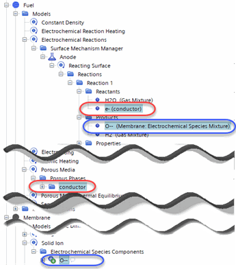

    1. Right-click the Reaction 1 > Reactants node and select a reactant. Repeat this step until all reactants are selected.
    2. Right-click the Reaction 1 > Products node and select a product. Repeat this step until all products are selected.
  2. Define the surface/region upon which the mechanism is applied.
    Surface Type
    Interface

    (recommended when using the Porous Media model)

    Select the Interfaces > [reactive interface] > Physics Conditions > Electrochemistry Mechanism Option node and set Mechanism to the [Electrochemical Mechanism] that is required.
    Boundary Select the Region > [fluid region] > Boundaries > [boundary] > Physics Conditions > Electrochemistry Mechanism Option node and set Mechanism to the [Electrochemical Mechanism] that is required.
    Region

    (for homogenized, that is distributed, non-resolved interfaces)

    Select the Region > [fluid region] > Physics Conditions > Electrochemistry Mechanism Option node and set Mechanism to the [Electrochemical Mechanism] that is required.
  3. If you choose to work with non-default values of Phase Interaction Area Exponents, select the Phase Interaction Area Exponents node and set Phase exponent values, see Phase Interaction Area Exponents. Typical values for Phase Interaction Area Exponents range between 0.3 to 3. Setting the exponent value to zero makes the chemical reaction independent from the phase volume fraction changes.
  4. Finalize any remaining settings for the region types and the conditions at the regions, boundaries, or interfaces.
    When using the Electrochemical Species model, porous baffle interfaces are not allowed.
  5. To define initial conditions for the electric potential, do one of the following:
    • If you want to specify the electric potential manually, select the [physics continuum] > Initial Conditions node and set the values for the electric potential.

      Simcenter STAR-CCM+ uses values that you set for the electric potential initial conditions everywhere.

    • If you want to let Simcenter STAR-CCM+ automatically initialize the electric potential, select the Solvers > Electric Potential > Expert Initialization node and set Method to Presolve. Prior to running the electric potential presolver, Simcenter STAR-CCM+ initializes the electric potential using a parts-based or region-based approach—dependent upon the set-up. For more information, see Expert Initialization.
  6. Set up Scenes and Plots to visualize the solution.
    For example, you can visualize the following field functions, among others, in a scalar scene or plot them on an x-y plot:
    • charged species mobility of specific electrochemical species
    • electric current density
    • electric potential
    • electrochemical reaction rate of a specific electrochemical reaction mechanism
    • migration flux of specific electrochemical species
    • molar concentration of specific electrochemical species
    • number density of specific electrochemical species
    • molecular diffusivity of specific electrochemical species
    • bulk substance electrochemical reaction flux of a porous phase
    • surface/average molar concentration
    To check energy conservation, add reports for electric power flux and energy loss then create monitors and a single plot from these reports. For more information, see the Electrochemistry: Solid Oxide Fuel Cell Tutorial.
  7. Run the simulation.