When remeshing happens, the mesh pipeline ensures that the pump is
positioned in a correct position. Besides, due to the small gaps you apply Directed Mesh to
reduce the cell count in the axial direction of the pump.
You define two motion Transform operations, one Substract operation and one
Directed Mesh operation for the gerotor volume.
-
First, you define two rotational motions for the inner and outer rotors. Their
rotational speeds match the number of teeth—the outer rotor with 12 teeth rotates a bit
slower than the inner rotor with 11 teeth.
-
To define the rotation for the inner rotor, right-click the node and select .
-
Rename the Rotation node to
Rotation_inner and set its properties as follows:
| Node |
Property |
Setting |
| Rotation_inner |
Rotation Specification |
Rotation Rate |
 Rotation
Rate Rotation
Rate |
Rotation Rate |
1090.90909
rpm |
 Rotation Axis Rotation Axis |
Direction |
[0.0,0.0,1.0] |
| Origin |
[0.0,0.0,0.0] m |
-
To define the rotation for the outer rotor, right-click the node and select .
-
Rename the Rotation node to
Rotation_outer and set its properties as follows:
| Node |
Property |
Setting |
| Rotation_outer |
Rotation Specification |
Rotation Rate |
 Rotation
Rate Rotation
Rate |
Rotation Rate |
1000
rpm |
 Rotation Axis Rotation Axis |
Direction |
[0.0,0.0,1.0] |
| Origin |
[-0.0031,0.0,0.0] m |
-
You define two motion transforms for the inner and outer rotors that follow their
respective rotations. Therefore, the rotor geometry is always positioned correctly
whenever a remesh takes place.
-
Right-click the node and select .
-
In the Create Transform Operation dialog, select
the part Inner and click OK.
-
Rename the Transform node to
Transform_inner.
-
Right-click the node and select .
-
Select the node and set Motion to
Rotation_inner.
-
Repeat the steps above to define a Transform_outer operation
with the part Outer.
-
Right-click the node and select .
-
Select the node and set Motion to
Rotation_outer.
To generate the wetted volume, you subtract the inner rotor volume
from the outer rotor. As later you apply a Boundary
Plane constraint for the morpher, you extend the
Part Surface in the direction
normal to the Boundary Plane.
Extending the surface ensures that the surface and the plane intersect
correctly.
-
To extrude the Inner part in both directions:
-
Right-click the node and select Repair
Surface.
-
In the Surface Repair Options, keep default
settings and click OK.
-
Double-click to select all the Faces to be extruded in the
+y direction as follows:
-
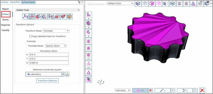
After selecting the faces, in the Global tools, select
Transform selected entities and set Transform
Mode to Translate.
-
Set Translation Vector to [0.0, 0.0,
0.005] m and click Transform Selection.
-
Repeat the steps with the opposite faces and Translation
Vector
[0.0, 0.0, -0.005]m.
-
To generate the wetted volume, you define a Subtract operation
between outer and inner rotors:
-
Right-click the node and select .
-
In the Create Subtract Operation dialog, select
the parts Inner, Outer as Input
Parts and Outer as Target Parts and click OK.
-
Select the node and activate the expert option Perform CAD Boolean.
-
Select the node and, in the Tessellation Options
dialog,set Tessellation Density as
Very Fine.
A very fine tessellation helps to obtain a better surface
representation of the gear walls.
-
To rename the output part Subtract, select the node and rename it to PumpFluid.
-
To mesh the part PumpFluid, you define a directed mesh operation
with prism layers. Using the trimmed cell or polyhedral meshers would generate large cell
counts due to the small gaps between rotors. With a directed mesh you can generate
stretched cells in the gaps that reduce cell count.
-
Right-click the node and select .
-
In the Create Directed Mesh Option dialog, select
the part PumpFluid and click OK.
-
Select the node and set the part PumpFluid.Outer.top as Source
Surfaces.
-
Select the node and set the part PumpFluid.Outer.bottom as Target Surfaces.
-
To add a source mesh used in volume generate, right-click the node and select Automated Source
Mesh.
-
In the Part Collection For This Source Mesh
dialog, select the part PumpFluid and enable the following
meshers and click Ok.
- Quadrilaterial Mesher
- Prism Layer Mesher
-
Select the node and set the following properties:
| Node |
Property |
Setting |
| Base
Size |
Base Size |
0.001
m |
| Minimum
Surface Size |
Percentage of Base |
0.5 |
| Prism Layer Controls |
Gap Fill
Percentage |
35.0 Specifies the maximum allowable prism
layer total thickness in percentage of an intersection distance—the normal
distance between two boundaries. |
| Minimum Thickness
Percentage |
0.01 Specifies the minimum allowable prism
layer total thickness. Below this value the thickness is forced to zero.
Due to the small gaps between rotors, this value is set to the
minimal possible value 0.01. |
| Prism Layer Reduction Percentage |
0.0 Controls the point at which the number of
layers is reduced. See also: 什么是层减少? Zero indicates
that no layer reduction is allowed. |
 Prism Layer Total
Thickness Prism Layer Total
Thickness |
Percentage of
Base |
10.0 |
-
Right-click the Mesh Distributions node and select
New Volume
Distribution.
-
In the opened diaglog Parts for creating a new mesh
distribution select the part PumpFluid and click
Ok.
-
Select the node and set the Number of
Layers to 10.
-
Save the simulation with the name
geroter_run.sim.


