Acoustic Modal Analysis Workflow
You perform an acoustic modal analysis from a previously converged solution.
| 注 | If required, you can automate the Acoustic Modes solution using the Simulation Operations feature. See Solve Accoustic Modes. |
- Run a Simcenter STAR-CCM+ simulation to convergence using the following physics models:
Group Box Model Space Any Time Steady Material One of: Gas, Liquid, Multi-Component Gas, or Multiphase. Multiphase (only when a multiphase model is selected). Any (except Two-Phase Thermodynamic Equilibrium). Reaction Regime (only when Multi-Component Gas is selected) Any Flow Any Equation of State One of: Ideal Gas, Real Gas, or User-Defined EOS. (Any equation of state model that provides Speed of Sound). Energy Any Viscous Regime Any - Within the same simulation that has a converged solution, for the relevant physics continuum, you add the Acoustic Modal Analysis model to the previously selected models.
- Right-click the node and select Select Models.
- In the [physics continuum] Model Selection dialog, in the Optional Models group box, in addition to the previously selected models, select Acoustic Modal Analysis.
- Select the node and set values for the following properties:
Property Setting Number of Modes Specify the number of modes that Simcenter STAR-CCM+ computes. For [n] modes, this represents the [n] lowest frequencies.
Shift Frequency Specify the lowest frequency above which Simcenter STAR-CCM+ computes the nearest acoustic modes. Flame Transfer Function Available only when the Reacting model is selected in the [physics continuum].
- Zero Source
- Select this option to ignore the effect of the flame.
- N-Tau
- Select this option to allow Simcenter STAR-CCM+ to account for the unsteady heat release in the flame by using the interaction indexes and time delays that you specify within the [n-tau flame transfer function] sub-nodes. You can specify multiple n-tau flame transfer functions to model the response of the flame to several upstream fluctuations, such as multiple inlets.
- User N-Tau
- Select this option to manually specify profiles for the interaction index and time lag. Simcenter STAR-CCM+ uses these to account for the unsteady heat release in the flame. You can create further user specified n-tau flame transfer functions to model the response of the flame to several upstream fluctuations, such as multiple inlets.
For further information, see Acoustic Modal Analysis Properties.
- For each boundary, select the node and set the Method as required.All methods are available for all boundary types, although some methods are better suited for specific boundary types.
Acoustic Impedance Specification Method Use Boundary Type Perfectly Reflecting When acoustic pressure is perfectly reflected from a boundary.
For example, at fully rigid walls, or at reflecting inlets where an inflow velocity is imposed which zeroes any velocity fluctuations.
Inflow, Outflow, Wall or Symmetry Zero Acoustic Pressure When there are no pressure fluctuations at the boundary (that is perfectly reflective).
For example, at fully reflecting outlets where a specified pressure is imposed which zeroes the pressure fluctuations.
Inflow or Outflow Specified Impedance To set the magnitude and phase of reflections at a boundary that are independent of the acoustic frequency.
For example, when modeling the effect of unresolved geometry beyond the outlet—such as a turbine vane downstream of a combustor.
Inflow, Outflow, or Walls Quadratic Impedance To set specified impedance boundary conditions where the magnitude and phase can be specified as a quadratic function of the acoustic frequency.
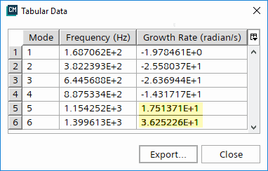
Inflow, Outflow, or Walls - Right-click the node and select Solve for Acoustic Modes.The acoustic modal solver computes the modes and displays a table in the output window. This table contains details of the frequency and growth rate for each acoustic mode.
注 If the solution does not converge, select the Acoustic Modal Solver node, then gradually reduce the Tolerance Scaling Factor and increase the Iteration Scaling Factor until the solution converges.
- To view or export the Acoustic Frequency Table, do the following:
- To visualize the acoustic mode shapes, do the following:
- Create a scalar scene and set Parts to the region in which to display the modes.
- In the graphics window, right-click an empty space and select .
- Select the node and set the Function to Acoustic Pressure Normalized.
- Select the node and use Acoustic Mode to select the mode number to display.
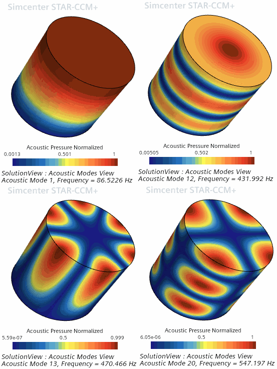
注 The Acoustic Pressure Normalized field function is only available when using the . Otherwise, you can create a scalar scene/displayer for each acoustic mode and use the different Acoustic Pressure Normalized - Mode [n] field functions in each scene/displayer. For example, the following images show a sample of acoustic mode shapes for a closed cylindrical domain: The first acoustic mode shown above (top left), acoustic mode 1, shows the lowest frequency mode—which corresponds to the half wavelength.
