Setting Up and Running the Design Sweep Study
After running the simulation, you create a Design Manager project that runs a design sweep on the spoilers.
-
Right-click the root node of the
SpoilerReplacement_run simulation and select
Create Design Manager Project.
Save the Design Manager Project as SpoilerDesignSweep.dmprj.
- In the Design Manager project tree, right-click the Design Studies node and select New.
- Rename the Design Study to Spoilers Sweep.
-
Select the
node and click
Edit Parameter
 .
.
-
In the Input Parameters dialog, select
PartReplacement and click
OK.
This action allows Design Manager to use the file global parameter you created previously.
-
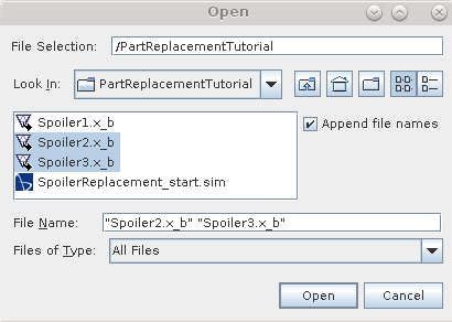
To add Spoiler2 and Spoiler3 to
the design study:
In this tutorial, you set the coefficient of lift and drag as responses so that you can monitor their values for each spoiler design.
-
To add
Responses to the design study:
-
Select the
node and click the
Custom Editor (
 ) for
Responses.
- In the Responses dialog, select CD (coefficient of drag) and CL (coefficient of lift).
- Click OK.
-
Select the
node and click the
Custom Editor (
-
Select the data that you want to post-process:
-
Select
node and click the
Custom Editor (
 ) for
Scenes.
- In the Scenes dialog, select Vector Scene 1 and click OK.
-
Select
node and click the
Custom Editor (
- Select the node and deactivate Clear History.
- Save the Design Manager project.
-
Right-click the
node and select
Run Study.
The Output Table window displays the properties of each design.
-
To visualise the post-processing data of the case:
- In the Output Table window, right-click Design 1 and select .
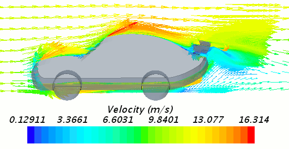
You can follow this step to visualise Design 2 and Design 3. The following image shows Vector Scene 1 for Design 1:

