VOF Waves Guidelines
This section describes the set-up and analysis procedures applicable to Volume Of Fluid (VOF) wave simulations.
See VOF Guidelines for general recommendations on VOF simulations.
Meshing Considerations
Use the following meshing guidelines, where applicable:
- Mesh near free surfaces must be able to resolve both amplitude (wave height) and wavelength. This objective requires a cell size appropriate for the wave under consideration.
- You can increase grid size with distance from the free surface, since wave effects decay exponentially with depth.
- As ships and similar bodies generate a wide spectrum of waves, it is not feasible to resolve the smallest wavelengths. Choose the minimum wavelength that you want to resolve.
- If you are using irregular or superposed waves, you must expect to use a fine mesh to resolve small waves.
- If you are using flat wave, set the mesh to capture the waves that are generated in the wake. Also, adjust the mesh such that the flat free surface coincides with grid surface (that is, avoid partially filled cells at the undisturbed free surface).
- Use the wave model appropriate for the given wave steepness and water depth. See Modeling VOF Waves for the available types waves.
- In most cases, the best size of
time-step depends on speed of wave propagation. However, small time-steps can be
required for breaking waves, or for cases where the mesh is fine in the vertical
direction. In these cases, vertical motion of the free surface is more important
than wave velocity.
注 Simulations with second-order discretization diverge if the free surface moves half a cell or more per time-step. - The best time-step size for ships and offshore structures depends on wave properties and whether additional detailed flow features must be resolved. For example, when modeling wave impacts on an offshore platform, the simulation can require smaller time steps so that it captures maximal pressures or forces.
- If you know the amplitude and
wavelength or period of the VOF waves, use the following steps:
- In the Mesh operation, select the Trimmed Cell Mesher model.
- In the Trimmed Cell Mesher node model properties, activate Perform Mesh Alignment.
- Select .
- Set the Location property to the waterline at the front of the body in the simulation.
- Select and create a block that covers the entire domain in the X and Y directions. Also extend the block far enough in the Z direction to enclose all the waves, with 10% additional space.
- Create a Volumetric Control for the block.
- In the Mesh operation, under , set the following properties, in order:
Node Property Value Customize Isotropic Size Deactivated Customize Anisotropic Size Activated Relative/Absolute Absolute Custom X Size Activated Custom Y Size Activated Custom Z Size Activated  Absolute X Size
Value 1/80th to 1/100th of the wavelength  Absolute Y Size
Value 1/80th to 1/100th of the wavelength  Absolute Z Size
Value About 1/20th of the wave height The X and Y axes lie on the free surface, with the Z axis normal to it.
The mesh resolution along the wave does not have to be as high as in the wave propagation direction (except for short-crested waves).
- Set the time-step for the
Implicit Unsteady Solver according to this equation:
time-step =
where is the wave period and is the number by which you divided the wavelength to get Absolute X Size. For instance, if you used 1/80 of the VOF wavelength, = 80.
The above steps apply best to first- and fifth-order waves.
Turbulence Damping
In some cases, the two-equation turbulence models generate excessive turbulent viscosity beneath VOF waves which results in a rapid production of turbulent kinetic energy and eddy viscosity. This influences wave dynamics, causing a gradual decrease in wave amplitude over multiple wavelengths. To control excessive turbulent viscosity in these simulations, you are advised to set Realizability Option to Vorticity Limiter for the two-equation turbulence model that you are using (K-Omega or K-Epsilon). For further information, see Turbulence Damping for Free-Surface Waves (K-Omega) and Turbulence Damping for Free-Surface Waves (K-Epsilon).
Boundary Conditions
Use the following guidelines, where applicable:
- Use the inflow boundary condition whenever possible. Make sure current and wind velocities vectors point from the inlet to the outlet.
- Generally, use the no-slip condition on side boundaries.
- For open water or side boundaries, slip-wall or symmetry conditions are appropriate for side boundaries.
- For bottom boundaries, inlet, no-slip, or slip wall boundaries are appropriate, but never symmetry boundaries.
- Eliminate spurious wave reflections.
These reflections most commonly happen at boundaries and sudden mesh
transitions.
- To avoid internal reflections, avoid changes in grid resolution in the vertical direction within the wave zone.
- To avoid wave reflections at boundaries, use a large damping zone, initially, then reduce it to about half the volume after 5–10 time-steps. See VOF Wave Forcing and Wave Damping.
- For each wave, in the Physics
continuum, under Initial Conditions, set the following
values:
Node Property Value Pressure Method Field Function Scalar Function Hydrostatic Pressure of [wave] Velocity Method Field Function Vector Function Velocity of [wave] Volume Fraction Method Composite  (or other heavy fluid)
 Method Field Function Scalar Function Volume Fraction of Heavy Fluid of [wave]  (or other light fluid)
 Method Field Function Scalar Function Volume Fraction of Light Fluid of [wave] - For all inlet boundaries under , set the following values:
Node Property Value Method Magnitude + Direction Method Field Function Scalar Function Velocity of [wave] Method Composite  (or other heavy fluid)
 Method Field Function Scalar Function Volume Fraction of Heavy Fluid of [wave]  (or other light fluid)
 Method Field Function Scalar Function Volume Fraction of Light Fluid of [wave] Method Composite At the outlet, specify a pressure boundary. Set the pressure and volume fraction to the hydrostatic pressure and the volume fraction of the flat wave.
 (or other heavy fluid)
 Method Field Function Scalar Function Volume Fraction of Heavy Fluid of [wave]  (or other light fluid)
 Method Field Function Scalar Function Volume Fraction of Light Fluid of [wave] Method Field Function Scalar Function Hydrostatic Pressure of [wave] 注 For simulations with more than one VOF wave, you can define the initial conditions, and/or boundary conditions using Linked VOF Wave field functions instead of VOF Waves field functions. This reduces the time required for simulation pre-processing by simplifying switching between VOF waves.
The Physics of Wakes
When setting up simulations using VOF waves, bear in mind the following features of wave physics:
- The energy of a wave is proportional to
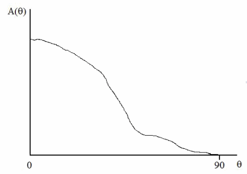
the square of the wave amplitude. If possible, obtain the amplitude spectrum for
the ship. This profile relates the amplitude of waves
to the angle
between the path of the ship and the path of the
wave. Use this information to decide which waves must be resolved and which can
be ignored.
Example amplitude spectrum:

- The wavelength of wake waves is also
related to
.
For a ship in steady forward motion:
where is the speed of the ship.
- Under , in the properties for the individual wave nodes, set Light Fluid Density and Heavy Fluid Density to the correct values. Do not assume that the default values are correct for your simulation.
- In simulations that last many wave periods, to get the best wave propagation result, increase the Angle Factor property of the Volume of Fluid (VOF) model from the default of 0.05 to 0.15.
Setting the First Wave Front Position
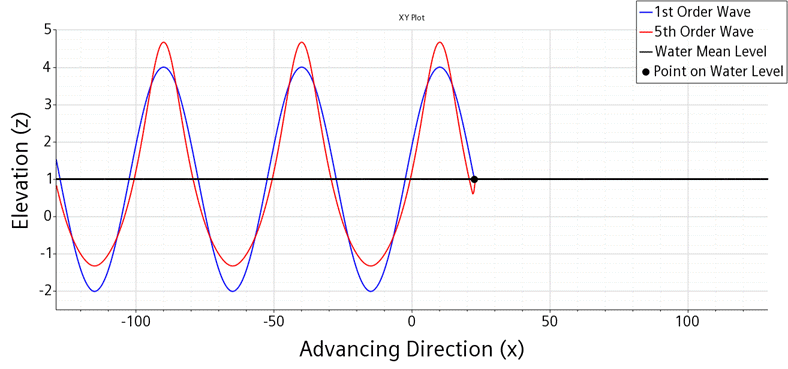
When First Wave Front Setting is activated, the Point on Water Level is located at a distance of wavelength/4 in front of a wave peak. For a first-order wave, that point lies at the free surface. However, this is not the case for higher-order waves, as illustrated below:

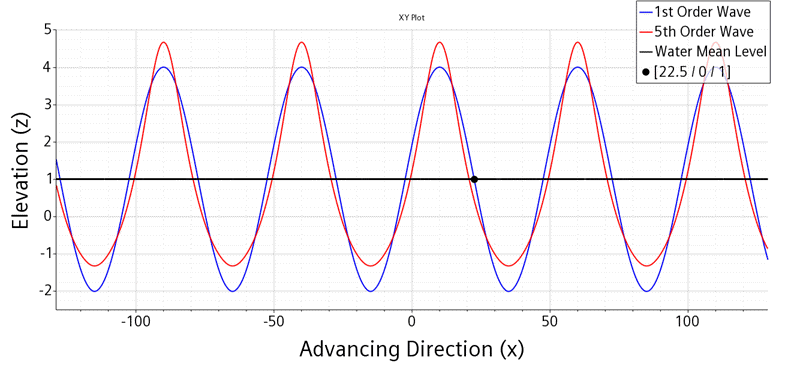
In the above example, the vertical direction is given by z and the advancing direction is given by the x-axis. The mean water level is at z = 1 m. The wavelength is 50 m and a wave peak is positioned at x = 10 m with a Point on Water Level = [22.5/0/1] m. This diagram shows the Point on Water Level is at the free surface for the first-order wave but not for the 5th order wave.
If a wave is generated in the whole domain and you want a wave peak to be positioned at x = 10 m, you can specify the x-coordinate of the Point on Water Level in the advancing direction as an integer multiple of the wavelength plus the wavelength/4 (in this case 50/4 = 12.5). For example, [72.5/0/1], [122.5/0/1], [172.5/0/1], and so on.
