Volume Of Fluid (VOF) Multiphase Model Reference
Volume Of Fluid (VOF) is a multiphase model that is suited to simulating flows of several immiscible fluids on numerical grids capable of resolving the interface between the phases of the mixture.
| Theory | See Volume of Fluid Method. | ||
| Provided By | |||
| Example Node Path | |||
| Requires |
|
||
| Properties | Key properties are: Convection, Face Density Reconstruction | ||
| Activates | Physics Models | Viscous Regime | |
| Model Controls (child nodes) |
HRIC HRIC Gradient Smoothing Adaptive Mesh Interpolation Modified HRIC Interface Detection |
||
| Initial Conditions |
See Initial Conditions. |
||
| Region Settings | Phase Conditions:
See Region Settings. |
||
| Report Options | See Free Surface Quality. | ||
| Solvers |
Segregated VOF |
||
| Field Functions | See Field Functions. | ||
Volume of Fluid (VOF) Properties
- Convection
- Specifies the
discretization scheme of the convective flux in the VOF transport equation.
Method Corresponding Method Nodes 1st-Order Selects the first-order convection.
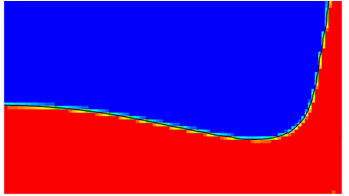
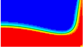
None. HRIC The HRIC scheme is used in VOF simulations to maintain a sharp interface between the participating fluid phases.
HRIC The following properties are available:
- Sharpening Factor
- This
factor is used to reduce numerical diffusion in the
simulation. The valid values are 0.0 through 1.0.
When the sharpening factor is set to 0.0, there is no reduction in numerical diffusion. This value is the default because, in most cases, the recommended 2nd-order discretization scheme is sufficient to achieve a sharp interface between the two phases.
When the sharpening factor is set to 1.0, there is no numerical diffusion and, therefore, a very sharp interface is obtained.
For some flows, such as surface-tension dominated flows or tank sloshing flows, it is recommended that you increase the sharpening factor to improve the resolution of the interface between the phases. However, this additional sharpening can result in a non-physical alignment of the free surface with the grid lines.
If a non-zero value is specified, an additional term (Eqn. (2585)) is added to the VOF transport equation (Eqn. (2584)). This value is in Eqn. (2585).
Raising the sharpening factor increases the runtime necessary to preserve volume conservation.
- Angle Factor
- The angle factor in the HRIC convection discretization scheme for interface tracking. If the free surface is not smooth and not following the grid lines, increase its value.
- CFL_l
- The lower Courant number limit in the HRIC convection discretization scheme. This value is in Eqn. (2594).
- CFL_u
- The upper Courant number limit in the HRIC convection discretization scheme. This value is in Eqn. (2594).
- Enable HRIC Gradient Smoothing
-
Uses a smoothed gradient to predict the upwind-upwind value in the HRIC scheme. This reduces the spurious oscillations that can appear in the volume fraction field In some situations, particularly when the mesh has a large aspect ratio.
Available when the Adaptive Mesh model is selected
- Option
-
Specifies the interpolation strategy for mapping the volume fraction field from coarse to fine cells. The following options are available:
- Injection: uses zero order
interpolation to map the volume fraction field
from coarse to fine cells. This is the default.
If the Free Surface Mesh Refinement criterion is used, interface cells are not marked for refinement. Only the cells near the interface are marked.
- Sharp Reconstruction: uses
sharp interpolation of the volume fraction field
based on interface reconstruction. The volume
fractions on the refined cells are obtained by
calculating induced cut volumes. For more
information, see Sharp Interface Reconstruction with Adaptive Mesh
Refinement.
If the Free Surface Mesh Refinement Criterion is used, both interface cells and the cells near the interface are marked for refinement.
- Injection: uses zero order
interpolation to map the volume fraction field
from coarse to fine cells. This is the default.
Modified HRIC The Modified HRIC is a composite scheme that uses the angle factor to blend the downwind, QUICK and upwind differencing schemes. This non-linear blend of differencing makes it less prone to (mesh-dependent) perturbations as it significantly reduces the contributions from the downwind scheme alone. As such, by default, the modified HRIC scheme, as a less compressive version of the HRIC scheme, will lead to smoother but also more diffusive solutions than the default HRIC scheme. However, it is also possible to adjust the level of compressiveness of the scheme and consequently, the sharpness of the interface.
The modified HRIC scheme is beneficial for free-surface flow VOF simulations, with a particular focus on flows that are characterized by traveling or stationary waves.
Modified HRIC The following properties are available:
- CFL_l
- The lower Courant number limit in the Modified HRIC convection discretization scheme. This value is in Eqn. (2594).
- CFL_u
- The upper Courant number limit in the Modified HRIC convection discretization scheme. This value is in Eqn. (2594).
- Interface Sharpness
-
Specifies the options for the level of compressiveness of the scheme in terms of the Downwind Limit above which the Modified HRIC scheme uses downwind differencing only. This is in Eqn. (2592).
The following options are available:
- Default—the default modified HRIC differencing scheme, a less compressive version of the HRIC scheme. It is equivalent to a downwind limit value of .
- Low—low interface sharpness, that is, a large downwind limit equivalent to a value of .
- High—high interface sharpness, that is, a small downwind limit equivalent to a value of . This option is more compressive than defaults and leads to a sharper fluid interface.
- Specified—activates the property. Use this parameter to specify the downwind limit value to increase or decrease the sharpness or diffusion of the fluid interface.
- Downwind Limit
- Available when the Specified interface sharpness method is selected.
- Face Density Reconstruction
-
Sets the discretization scheme to reconstruct density at internal faces.
Method Corresponding Method Nodes - 1st-Order
-
Uses first order face density reconstruction. This discretization scheme is computationally cheaper, but less precise. This option is the default selection.
This option can be used to reduce the simulation time for simulations where a high level of consistency between different transport equations is less important.
None. - 2nd-Order
-
Uses second order face density reconstruction. This discretization scheme is computationally more expensive, but offers a high level of consistency between all transport equations.
This option should be used for compressible simulations (that is, if the Mach number exceeds about 0.3).
None.
Interface Detection Properties
- Sharp Interface Thickness Criterion
- Specifies the number of
cells up to which an interface is identified as sharp. This is
in Eqn. (315).
The identification of the sharp cells is based on the magnitude of the volume fraction gradient . A cell is recognized as sharp when the following condition is met:
(315)where is the spatial component of the maximum volume fraction gradient that is achievable on the given cell and is a user-specified parameter representing the number of cells up to which the interface is regarded as sharp. The default value is 5.
- [Lower, Upper] Interface Volume Fraction Range
-
Specifies the lower and upper volume fraction limits that define a smeared cell. Smeared cells are cells that do not meet the sharpness criterion in Eqn. (315), but still contain a substantial volume fraction within user-defined limits that are detected according to the following condition:(316)
where and are the lower and upper bounds of the interface detection volume fraction range, respectively, and is the volume fraction. The default values are [0.01, 0.99].
HRIC Gradient Smoothing Properties
When Enable HRIC Gradient Smoothing is activated, a smoothed gradient is used to predict the upwind-upwind value in the HRIC scheme.
See Interface Smoothing.
- [Min, Max] Gradient Smoothing Steps
-
Controls the minimum and maximum number of smoothing steps that are applied to the volume fraction gradient. The default values are Min = 0 and Max = 20.
If Min = Max, exactly Min smoothing steps are performed. If both Min and Max are 0, no smoothing is performed and the standard HRIC method is retained. If Min < Max, a locally adaptive number of smoothing steps is performed.
- Reference Length Scale Factor
-
Defines the reference length scale against which curvature fluctuations between adjacent cells are evaluated. The default value is 10. A smaller factor leads to fewer local smoothing steps, a larger factor leads to more smoothing steps.
Initial Conditions
- Volume Fraction
Region Settings
The following setting applies to each phase and also to each fluid region.
Each phase momentum source is added to the region (the fluid mixture) momentum source (see Eqn. (2588)). The phase momentum sources are also taken into account, along with the gravity force and inertial force, when calculating the Drag-Based Slip Velocity (see Eqn. (2895)).
- Momentum Source Option
-
Method Corresponding Physics Value Nodes - None
- Specified
- Adds a specified momentum source to the momentum equation.
When the Specified method is selected:
- Momentum Source
- Momentum Source Velocity Derivative
The following settings apply to fluid regions.
Field Functions
When the Volume of Fluid (VOF) model is activated, the following field functions become available:
- Absolute Total Pressure of [phase]
- The pressure that results from isentropically bringing the flow to rest in the absolute frame of motion, defined as , where and are the Total Pressure and the Reference Pressure for each phase.
- Free Surface Quality Indicator
-
The identification of sharp and smeared cells is based on the Interface Detection that is part of the Volume of Fluid (VOF) Multiphase model.
- Total Pressure of [phase]
- The absolute total pressure minus the reference pressure defined. The total pressure is specified per phase.
- Total Temperature of [phase]
- The temperature that is obtained from bringing the fluid to rest. The total
temperature is specified per phase, using the equation of state of the phase
under consideration.
For incompressible fluid:
For compressible fluid:and


