Using the Time-Accurate Approach with the Virtual Disk Trim Option
When using the Blade Element Method with the Virtual Disk Trim Option, the trim solver calculates the control inputs—the required collective pitch, lateral cyclic pitch, and longitudinal cyclic pitch to achieve the desired thrust and moments you specify.

To create a reasonable initialization, you first run the
virtual disk simulation with time-average approach using steady time
model.
- Specify the virtual disk geometrical properties, which describe the blade geometry. See Blade Element Method Reference.
-
To pre-run the steady simulation:
- Right-click on the node, select Select Models and switch the time model to Steady.
- Select the node and set Source Term Distribution to Time Average.
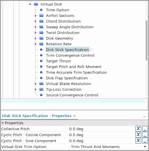
- Select the node, set the initial pitch angles and activate the Virtual Disk Trim Option with only thrust or with thrust and moments. See Disk Stick Specification.
To visualize the solution, you are advised to create a single plot with the following reports with iteration as monitor trigger. See 报告虚拟盘体结果 and Virtual Disk Report Reference.- Virtual Disk Force report in the Z direction of the disk coordinate system for thrust (lift force).
- Virtual Disk Moment reports in the Y direction of the disk coordinate system for the pitch moment and in the X direction for the roll moment.
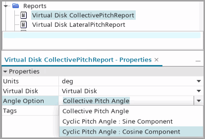
- Virtual Disk Angle reports
for the collective pitch, cyclic pitch: cosine component, and cyclic
pitch: sine component.

- Run the steady simulation until convergence.
After convergence, you modify the settings to use unsteady
time model with time-accurate approach.
- Right-click on the node, select Select Models and replace the time model with Implicit Unsteady.
-
Select the node and set the properties as follows:
Property Setting Time-Step A value, which corresponds to 1 degree rotation per time-step. Temporal Discretization 2nd-order -
Create another set of reports for thrust and moments. For all the reports,
activate Average
Force/Moment.
This option averages the report value over one revolution:

-
If required, create a Cyclic Time Unit to record the number of
revolutions:
You switch to the Time Accurate approach and continue running
the simulation:
- Select the node and set Source Term Distribution to Time Accurate.
- Select the node and set the properties described in Disk Stick Specification.
-
Run the simulation.
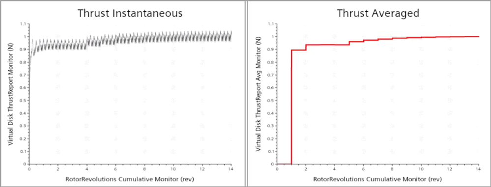
The plot of the thrust report is shown as follows:

The averaged signal is zero during the first revolution. The trim solver updates the values at the end of each revolution with the average of values collected during the last revolution.