Defining and Running the Reliability Study
You define a Robustness and Reliability study that assesses the impact of installation and manufacturing tolerances on design performance. To reduce the runtime for these studies, you predict the responses using the previously generated surrogate models.
Generally, for a reliability study to be accurate, the study must consider a high number (hundreds to thousands) of permutations around the best design. In this tutorial, you run the reliability study with 500 designs using the surrogate models computed previously.
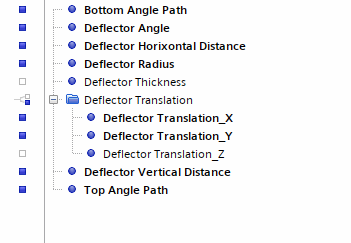
In this study, you apply a probability distribution to the input parameters. This probability distribution describes the likelihood that an input parameter will take a particular value. For the industrial exhaust manifold, you specify a relative triangular variation of ±3.5 % around the best design data points. You specify the data points as baseline values using the input parameter values that you obtained for the best design—Design 66.
To define the reliability study:
- Right-click the Design Studies node and select New.
- Rename the Design Study 2 node as Reliability.
-
Select the Reliability node and set the following
properties:
Property Setting Study Type Robustness and Reliability Evaluation Method Surrogates - Select the node and set Designs to Run to 500.
-
Specify the input parameters:
-
Specify the responses:
-
Right-click the Reliability node and select
Run Study.
The Output Table - Reliability - All tab opens showing you the state of each design, the input parameters, and the results. Despite the high number of designs to run, the study finishes fairly quickly due to the use of surrogates.


