Working with Species
The Species models are often used with combustion models, and so part of the process for setting up a simulation that involves a Species model also involves selecting a combustion model.
In general, however, when a Species model is active it is necessary to:
- Specify mixture components (the different species) and associated properties
- Set species initial distribution
- Set species fractions at relevant boundaries
When using Coupled Flow and Energy, the Coupled Species or Segregated Species models can be selected from the Species box of the Model Selection window after Multicomponent Gases are selected.
You can use Segregated Species, and therefore the Segregated Species solver, together with Coupled Energy and Coupled Flow. This is suggested for high speed multicomponent gases simulations to provide an important speed-up for the simulation. Examples:
- Rotating detonation reaction engines
- Ionization/dissociation during high-speed re-entry conditions
- Turbine CHT
- Scram jets
In such cases:
- Disable low-Mach preconditioning and ensure good convergence per time-step. (Use asymptotic convergence criteria with more than two orders of convergence for all flow equations.)
- Solve coupled flow and energy with segregated species.
To change from Coupled Flow and Energy with Coupled Species to a Coupled Flow and Energy with Segregated Species, edit the model selections:
- Deselect the current Equation of State model.
- Deselect the Coupled Species model.
- Select Segregate Species model.
- Re-select the Equation of State model.
If instabilities occur, revert to the fully coupled approach: Coupled Flow, Coupled Energy, and Coupled Species.
When selected together with the Coupled Flow model, the Segregated Species model uses the local time-step computed by the flow model for stabilization. The URF setting specified in the Segregated Species solver is ignored in this situation.
Specifying Mixture Components
A particular species is defined as one component in a multi-component gas mixture or liquid mixture. For a gas, the component collection is held within the Gas Mixture node of the Multi-Component Gas model node in the Models tree of the relevant physics continuum. These nodes are shown below. For liquids, this arrangement becomes the Liquid Mixture node of the Multi-Component Liquid model node.
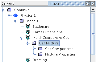
The components of the gas or liquid mixture are defined by adding new components to the Gas Components or Liquid Components node. This can be done manually as described in the section, Adding Mixture Components, or automatically by importing Chemkin-formatted data.
Each new component’s name and material properties are retrieved from the database with default property settings and values. You should review the default material property settings of the mixture as well as those of each new component. If necessary, change the settings of the mixture properties and then those of each new component accordingly (see Managing Multi-component Materials).
Note that:
- In order for a chemical species to be available for any given chemical reaction equation (see Defining Chemical Reactions) it must first be added to the Gas Components node.
- The order in which the mixture components are added is not important as all species are solved for.
- If the database does not include a component that is needed for your combusting mixture, make a local copy of the Simcenter STAR-CCM+ material database (file props.mdb) and add the required component and its physical properties to it.
- For an EBU or CFM combustion simulation, you most likely want to select Thermodynamic Polynomial Data (if it is available) as the method for the Specific Heat property of each mixture component. If you choose an alternative method for Specific Heat (for example, Constant or Polynomial in T), then you are required to provide Heat of Formation and Standard State Temperature values for that component as well.
Segregated Species and Coupled Species Model Properties
The Segregated Species and Coupled Species models share certain properties.
| Convection (Segregated Species only) | Selects the convection scheme that is used. | |
| 1st-order | Selects the first-order upwind convection scheme. | |
| 2nd-order | Selects the second-order upwind convection scheme. | |
| MUSCL 3rd-order/CD | Selects the hybrid MUSCL 3rd-order/CD convection scheme. Adds
the Bounded Differencing sub-node, where
you specify the Upwind Blending
Factor. The upwind blending factor specifies the proportion of upwind differencing, related to Eqn. (891). The default value is 1.0. The default provides the most robustness for the scheme. Reducing it would, in principle, increase accuracy. However, unless you are thoroughly familiar with the theoretical aspects of bounded differencing, do not change this property. The default value reflects optimization for accuracy and performance. |
|
| Flow Boundary Diffusion | Allows you to activate or deactivate diffusion at flow boundaries. Activated by default. | |||
| Multi-component Diffusion | When On, diffusive flux for a given component becomes a function of the mass fraction gradient of all other components. You can only calculate Molecular Diffusivity using the Binary Diffusion Coefficients method or Kinetic Theory Diffusivity method. This option is Off by default, in which case Fick’s Law is used to calculate the diffusive flux in the species transport equations instead of multi-component diffusion.. | |||
| Soret Effect |
The Soret effect accounts for mass diffusion due to the presence of a temperature gradient. For most problems, this effect is negligible; however, it can play a significant role in problems with large temperature gradients and problems with species of widely varying molecular weights. In practice, the Soret effect can be important for chemical vapor deposition, isotope separation and combustion of light components at low temperatures [35]. When activated, it is represented in the diffusive flux term of the species transport equations (see Eqns. Eqn. (1878) and Eqn. (1879)). This option is deactivated by default.
|
|||
| Secondary Gradients (Segregated Species only) | Neglect or include the boundary secondary gradients for diffusion and/or the interior secondary gradients at mesh faces. | |||
| On | Include both secondary gradients. | |||
| Off | Exclude both secondary gradients. | |||
| Interior Only | Include the interior secondary gradients only. | |||
| Boundaries Only | Include the boundary secondary gradients only. | |||
Species Boundary and Initial Conditions
The distribution of species within a continuum or across flow boundaries can be defined using either mass fraction or mole fraction. In Simcenter STAR-CCM+, the same set of nodes are provided for flow boundaries and initial conditions.
Use the Species Specification node within the Physics Conditions folder of a boundary or initial condition node to choose between mass fraction or mole fraction as the method for specifying species distribution. The corresponding value node, Species Mass Fraction or Species Mole Fraction, is added to the relevant Physics Values folder.
On wall boundaries, the Wall Species Option allows you to define the wall as impermeable to species transfer, or one having a specified mass fraction or specified flux.
Species Specification Node
This node is added to the Initial Conditions node of physics continua, and to the Physics Conditions node of flow boundaries, after you have selected components for the mixture.
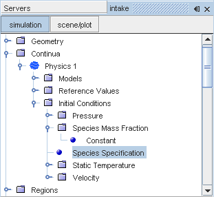
The single Method property of this node is used to switch between specifying the species distribution in terms of mass fraction or mole fraction.
| Method | Defines the basis on which initial species distribution is defined. | |
| Mass fraction | Mixture components are defined in terms of mass fraction. When this option is selected, a Species Mass Fraction sub-node is added under the Initial Conditions node (or the Physics Values node for a flow boundary). | |
| Mole fraction | Mixture components are defined in terms of mole fraction. When this option is selected, a Species Mole Fraction sub-node is added under the Initial Conditions node (or the Physics Values node for a flow boundary). | |
Using Species Mass Fraction
It is a scalar quantity that is used for both initial and boundary conditions, and is defined by one of the following options:
- Constant specifies a fixed value for all mixture components. The required values are entered in the Properties window as a scalar array profile in the order in which the components were defined.
-
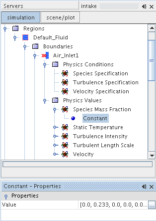
Alternatively, you may click the property customizer box, marked with an ellipsis and located to the right of the Value property array. This opens an input editor, shown below, which allows a more convenient way of entering these values as it lists component names side-by-side with the specified values.
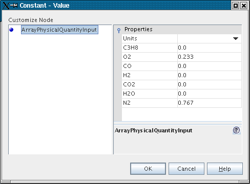
- Composite specifies the distribution of each component separately; distributions for each component are entered as scalar profiles.
-
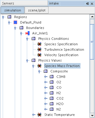
Both initial and boundary values that you specify are normalized prior to being used so that they sum to 1.0. Before normalizing, any value entered larger than 1.0 is set to 1.0. After this, normalization will be applied across all fractions. For example, [1.0, 2.0, 3.0] becomes [1.0, 1.0, 1.0], which normalizes to [0.333, 0.333, 0.333].
Using Species Mole Fraction
The mole fraction of a species is the ratio of its molar amount over the mixture molar amount, and is represented by the Species Mole Fraction node.
It is a scalar quantity that is used for both initial and boundary conditions, and is defined by one of the following options:
- Constant specifies a fixed value for all mixture components. The required values are entered in the Properties window as a scalar array profile in the order in which the components were defined.
-
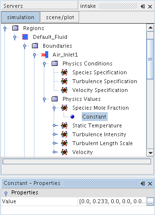
As for the Species Mass Fraction, the property customizer can be accessed by clicking the ellipsis to the right of the Value property array. This opens an input editor that identifies the different components in the array.
- Composite specifies the distribution of each component separately; distributions for each component are entered as scalar profiles.
-
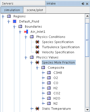
The Wall Species Option
For species transfer, this option defines a wall boundary as impermeable or as having a specified value or flux. The Coupled Species model or the Segregated Species model activates it.
Limitations:
- The bulk velocity of the wall species influx or outflux is negligible.
- The gain or loss of momentum due to wall species influx or outflux is negligible.
| Method | Defines the permeability of the boundary. | |
| Impermeable | Specifies the boundary as impermeable. | |
| Specified Flux | Specifies a species flux at the boundary. The energy that is associated with the wall species influx or outflux is appropriately added. Adds a Species Flux node to the Physics Values node. | |
| Specified Value | Specifies a species mass fraction at the boundary. Adds a Species Mass Fraction node to the Physics Values node. | |
Post-Processing
You can monitor the species flux at the wall with the Boundary Species Flux field function. To activate this field function, enable the Temporary Storage Retained expert property of the Segregated Species solver or the Coupled Implicit solver. This feature lets you verify your specification of the boundary conditions.The species flux is the mass flow rate of species added or removed per unit area. The Species Flux node is added when the Method property of the Wall Species Option boundary condition is set to Specified Flux. It is entered as a scalar array profile.