Morphing
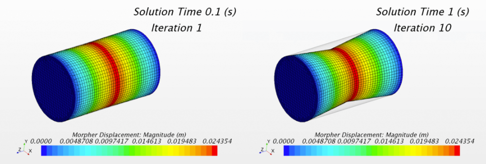
The morpher motion allows you to account for the effect of moving boundaries on your analysis in a transient simulation.
The morpher can be used, for example, to simulate the reciprocating motion of a piston in a cylinder—where the boundaries are not changing shape, but the mesh vertices must morph to accommodate the movement. The morpher can also be applied in cases where the shape of the boundaries is changing (for example, the build-up of ice on an aerofoil).
Overview of Morphing
The Morphing motion in Simcenter STAR-CCM+ redistributes mesh vertices in response to the movement of a set of control points, which you can consider as being a cloud of points overlaid onto the mesh domain. Control points, and their associated displacements, form the underlying framework that the morpher requires to generate an interpolation field.
Control points are generally defined using the coordinates of vertices that lie on mesh boundaries. Additional control points can be read in from a table file that you produce outside of Simcenter STAR-CCM+. Each control point has an associated distance vector that specifies the displacement of the point within a single time-step. The displacement can be set directly, or it can be calculated from the input of grid velocity, from which the displacement is calculated for a given time step.
- RBF: morphing is undertaken using multiquadratic radial basis splines. The RBF morpher utilizes a thin-out procedure to optimise the number of control points used.
- BSpline: morphing is undertaken using a fast, adaptive interpolation algorithm incorporating multilevel, cubic BSplines. On multiple processors, this method scales better than RBF in many circumstances. It can also better preserve meshes that contain prism layers.


| 注 | The morpher deals only with displacing the grid vertices—it does not deal with cell volumes, faces, or edges and, therefore, cannot compute mesh-quality metrics. The mesh quality should be checked before, during, and after the morphing process using Simcenter STAR-CCM+ visualization methods. Running the simulation with the physics models frozen (or deselected) reduces computational expense while you check the mesh quality. |
A high-level overview of the morphing procedure is as follows:
- The morpher collects control points, and their known displacements, from boundaries (and control point tables, if applicable) within the regions.
- (RBF only) Automatic Thinning (if activated) is applied to reduce the number of control points. Automatic thinning is activated by default.
- (RBF only) User-specified thin factors can be applied to reduce or increase the control point density.
- The Linear Fitter (if activated) updates the current location of the vertices.
- The control points, and their known displacements, are used to generate the interpolation field.
- The interpolation field is applied to all mesh vertices in the region.
- Some final adjustments are made to mesh vertices on or near boundaries.
Consistent Morphing for Edges
In contrast to most finite volume models in STAR-CCM+, the morphing module applies its boundary conditions on a vertex basis. When vertices are common to two or more boundaries the morpher must process and prioritize the boundary conditions in a consistent manner. To do so, the morpher requires displacement averaging and morpher boundary condition type priority.
- Fixed
- Displacement
- Rigid Layer Displacement, which marks rigid prismatic layers
- Edges between Displacement and Constraint
- Constraint
- Intersection Curves between two Constraints
- Floating
Edges between Displacement and Constraint
For edges between Constraint and Displacement boundaries, both boundary conditions are fulfilled—the vertices on the edge are moved with the given displacement and then projected back to constraints (plane, surface).
Intersection Curves between two Constraints
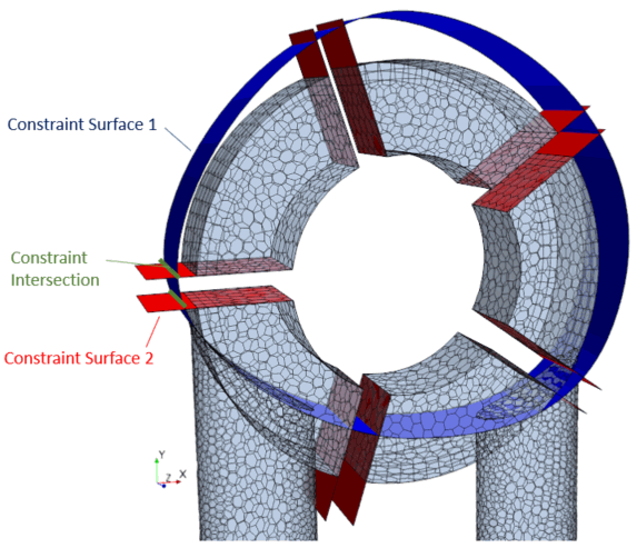
The mesh morpher solver detects the intersection curves between intersecting constraint surfaces and marks them as new constraints for edge vertices. The edge vertices are re-prioritized with the Morpher Boundary Condition Type, Constraint Intersection.

| 注 | To improve the automatic detection of constraint intersections, make sure that the constraint surfaces are geometrically intersecting. Two visually proximate constraint surfaces with touching edges sometimes cannot be intersected due to floating point rounding-off error. |
Constraint Representation
There are two possible surface representations for morpher constraint surfaces:
| Surface Representation | Constraint Surface Type |
|---|---|
| Surface defined by triangles | Part Surface |
| Triangulated Plane | |
| Initial Boundary | |
| Plane described by plane equation | Boundary Plane |
| Fixed Boundary Plane |
The BSpline morpher detects pair-wise constraint intersections for all constraint types.
The RBF morpher can only intersect a pair of constraint types whose surface is defined by triangles, that is, between Part Surface, Triangulated Plane and Initial Boundary.