Defining the Interfaces
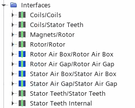
The starting simulation includes predefined interfaces between the solid regions. For the newly created fluid regions, you require additional interfaces. Each interface has either an in-place, periodic, or repeating topology.
As you are only modeling a quarter of the full machine, you
require periodic interfaces with rotational periodicity.
-
To create these interfaces:
-
Define the interfaces for the contacting regions:
The Airgap Remeshing model requires a repeating
interface where remeshing occurs, that is, between the stationary air gap and the
rotating air gap regions.
- Select the node and set Topology to Repeating.
- Select the node and set Method to Anti-Periodic.
-
Expand the Interfaces node and multi-select the
following interfaces:
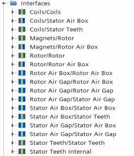
- Rotor Air Box/Rotor Air Box
- Rotor Air Gap/Rotor Air Gap
- Stator Air Box/Stator Air Box
- Stator Air Gap/Stator Air Gap
- Rotor Air Gap/Rotor Air Box
- Stator Air Box/Stator Air Gap
- Rotor Air Gap/Stator Air Gap
- Magnets/Rotor Air Box
- Rotor/Rotor Air Box
- Stator Air Box/Stator Teeth
- Coils/Stator Air Box
-
In the Multiple Objects - Properties panel,
set Contacts to Type is Part Surface
Contact.

-
Right-click the Interfaces node and select .

- Save the simulation.
