Generating the Mesh
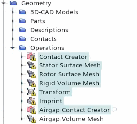
The starting simulation contains predefined operations for preparing and meshing the geometry. These operations include generating contacts between the parts, rotating the rotor air gap into its starting position, and generating a tetrahedral volume mesh for all parts.
-
Multi-select the first 7 mesh operations:

- Right-click one of the selected nodes and select Execute.
-
Under the node, select
 (Custom Editor) next to Parts.
-
In the Part Surface dialog, activate
Imprint and click OK.
Make sure you leave the remaining surfaces selected.
- Repeat the previous two steps for the node.
- Right-click the node and select Execute.
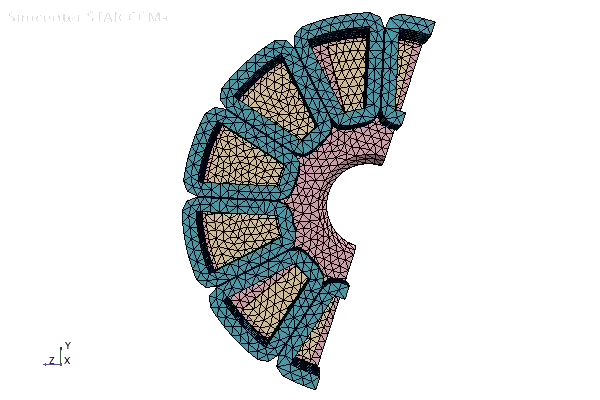
- Right-click the Scenes node and select .
-
Expand the node and set the following properties:
Node Property Setting Mesh 1 Color Mode Distinguish Regions  Parts
PartsParts Deactivate all Fluid regions and 
- Save the simulation.