Defining the Fluid Continuum and Specifying the Element Order
To model the air domain, you require a single physics continuum. The physics continuum contains the Airgap Remeshing model (to ensure a conformal mesh is maintained between the stationary and rotating portions of the air domain) and the Finite Element Magnetic Vector Potential.
To select the physics models:
- Right-click Continua, and select New Physics Continuum.
- Rename Physics 1 to Air.
-
For the physics continuum, , select the following models in order:
Group Box
Model
Space Three Dimensional Time Implicit Unsteady Material Gas Optional Models Electromagnetism Gradients (selected automatically)
Airgap Remeshing
Electromagnetism Finite Element Magnetic Vector Potential Eddy Current Suppression(selected automatically)
-
Select the node, and set Mesh Operations to Airgap
Volume Mesh.
By setting the Airgap Remeshing model to Airgap Volume Mesh, Simcenter STAR-CCM+ automatically re-executes the mesh operation every time-step. This ensures a conformal mesh is maintained in the air gap.
For the electromagnetic analysis, you use finite element models such as
the Finite Element Magnetic Vector Potential model. To
capture the physics with sufficient accuracy, while avoiding excessive mesh
refinement, you can increase the finite element order. In this case, you increase
the element order in the Magnets, Air,
and Stator Teeth continua. The higher order elements also
provide greater accuracy to specific models in each of the continua:
- Magnets—improve the accuracy of the loss calculations and captures the eddy currents in the magnets more accurately.
- Air—improve quality of flux density field to improve the torque calculations.
- Stator Teeth—improve the resolution of the laminated steel model without the need for a finer mesh.
To specify the element order:
-
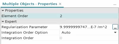
Multi-select the , , and nodes and set Element Order to
2.

Define the magnetic vector potential specification for the fluid
regions:
- Multi-select the , Rotor Air Gap, Stator Air Box, and Stator Air Gap and set Physics Continuum to Air.
- Multi-select the , , , and nodes.
- Right-click one of the selected nodes and select Edit.
-
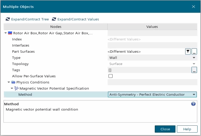
In the Multiple Objects dialog, expand the and set Method to Anti-Symmetric - Perfect Electric Conductor.

By setting the Magnetic Vector Potential Specification to Anti-Symmetric - Perfect Electric Conductor you ensure that no magnetic flux crosses the boundaries. This is achieved by setting the tangential component of the magnetic vector potential to zero. - Click Close.
- Save the simulation.