Modeling Fluid Film Flow

Simcenter STAR-CCM+ assumes that you are modeling a fluid film on the surfaces of a volume that contains a background fluid. While the background fluid occupies a regular region, the fluid film must flow in a three dimensional shell region.

Before setting up a fluid film analysis, you must already have a physics continuum defined with a single or multiphase flow model and associated fluid materials. You can model fluid films in a steady or an unsteady simulation.

For steady simulations, the following conditions apply:

  • Impingement, wave stripping to a Eulerian phase in a Eulerian Multiphase simulation, and Film-VOF phase interactions are not supported.
  • The Stabilised Film Thickness Equation must be activated in the Fluid Film Flow model.

    A steady fluid film setup sometimes has a zero coefficient matrix for the film thickness equation. This issue can occur when the film thickness, as well as the film velocity, are initially set to zero. When this issue occurs, the Stabilized Fluid Film Thickness Equation option must be activated in the Fluid Film Flow model in order to get the simulation to run.

A Fluid Film simulation can include effects such as impingement, film stripping, evaporation, condensation, and boiling. You can also model reactions between fluid film components, fluid film–gas interactions, and secondary current distributions that are due to electrochemical reactions.

To set up a Fluid Film simulation:

  1. Open the Physics Model Selection dialog for the physics continuum that provides the background fluid. From the Optional Models group, select the Fluid Film model.
  2. In the left panel of the Physics Model Selection dialog, right-click the Fluid Film > Fluid Film Phases node and select New.
    Simcenter STAR-CCM+ adds a film phase.
  3. Specify the film phase material:
    1. Select the Fluid Film > Fluid Film Phases > [film phase] node.
    2. In the right panel of the Phase Model Selection dialog, in the Material group box, select the material that is appropriate to your analysis.

      Although a fluid film usually comprises one or more liquid components, solid components can be included. Any solid components are modeled as particles suspended in the fluid.

      • Liquid

        Use this model for applications that involve film stripping to Lagrangian, Eulerian, or Dispersed phases.

      • Liquid-Solid-Gas Mixture

        Use this model for applications when a mixture of different thermodynamic states exists. The most common examples are mixtures of liquids and particulate solids, usually referred to as slurries.

      • Multi-Component Liquid

        Use this model for applications that involve boiling or evaporation and condensation.

    3. For Liquid-Solid-Gas Mixture and Multi-Component Liquid only, select the Reaction Regime.
    4. Select the Equation of State.
    5. In the Optional Models group box, choose the optional film phase models that are appropriate to your analysis.
    6. In the left panel of the Phase Model Selection dialog, right-click the fluid film phase and then click Select in Simulation.
      The Phase Model Selection dialog closes and the fluid film phase is selected in the simulation tree.
  4. Specify the film phase material components:
    • For Liquid, the default phase material is water. If you want to change it, right-click the Liquid > H2O node and click Replace With....

      In the Replace Material dialog, select the appropriate liquid material.

    • For Liquid-Solid-Gas Mixture, for each component that you want to add:

      Right-click the Mixture Components node, click Select Mixture Components, and then click the component type: Gas, Liquid, or Solid.

      In the Select Mixture Components dialog, select the appropriate material.

    • For Multi-Component Liquid, for each component that you want to add:

      Right-click the Mixture Components node and then click Select Mixture Components.

      In the Select Mixture Components dialog, select the appropriate liquid material.

  5. Set the film phase material properties to match the film that you wish to model:
    1. For each fluid film phase component, expand the Material Properties node and set the properties for individual components.
    2. For Liquid-Solid-Gas Mixture and Multi-Component Liquid only, expand the Material Properties node for the mixture and set the properties for the mixture.
  6. Select the [film phase] > Initial Conditions node and set the following:
    1. Select the Fluid Film Thickness node and provide a value or function for the initial thickness.

      The tutorial, Fluid Film: Liquid Film Flow, demonstrates how you can use a field function to define an initial thickness according to spatial location.

    2. For a multi-component phase, set the appropriate method on the Species Specification node and then specify the initial values of the mass fraction or molar fraction for each component of the phase.

      To improve convergence, you should always specify initial values of mass fraction or molar fraction, even if the phase is empty initially (that is, the initial Fluid Film Thickness is 0.0). For a phase that is empty initially, it is recommended that you set the initial mass fraction to the mass fraction values that the phase has when it enters the solution domain.

  7. Create the fluid film region on the surfaces of the containing fluid region:
    1. Expand the Regions > [containing region] > Boundaries node. Multi-select boundaries on which you expect the film to flow. Include boundaries that have no initial film, but which receive film during the simulation, for example due to impingement or condensation.
    2. Right-click one of the selected boundaries and select Create Shell Region.
      Simcenter STAR-CCM+ adds a new shell region to the simulation tree. In addition, Simcenter STAR-CCM+ creates an interface between the fluid region and the shell region, based on the original boundaries of the fluid region.
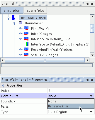
    3. Set the shell region continuum to specify the fluid film phase that is associated with the shell region.


      Once the shell region is connected to a fluid film phase, it becomes an active part of the simulation.

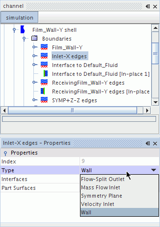
    4. Set up the shell region boundaries, interfaces, and physics conditions for the fluid film flow in the same way as for any other flow in Simcenter STAR-CCM+.

      The boundary type that you select applies the conditions appropriate to that type to the fluid film.


      Boundaries within the same fluid region belong to the same shell region.

    5. If fluid film passes from one shell region to another, join the two regions using an in-place interface.
    6. In the Physics Conditions > Initial Condition Option node, define the initial film conditions.
      By default, the shell region uses the global settings of the continuum. If you want to set different initial conditions for the shell region, select Specify Region Values, and then set the appropriate values under the Initial Conditions node.
    7. If you want to model a moving shell region, assign the appropriate motion or moving reference frame to the volume region from which the shell was created.
      The specified motion and reference frame are set in the Physics Values > Motion Specification node in the associated shell region. These settings are read-only in the shell region. The Lead Region property indicates the volume region that the shell region follows. This region is the volume region from which the shell region was created.
The fluid film model supports additional options that you can add to the simulation:
  • Films formed by vapor condensation and reduced by evaporation.
  • Films formed by droplet impingement and reduced by film stripping.
  • Fluid film reduced by boiling.
  • Passive scalar tracking of the Eulerian or Lagrangian phases in the continuum.
  1. Select the appropriate optional models in the physics continuum:
    • To model fluid film stripping or impingement, select the Multiphase Interaction and the Lagrangian Multiphase models. See Modeling Impingement or Modeling Film Stripping.
    • To model heat transfer or energy through the fluid film, select Coupled Energy or one of the Segregated Fluid Energy models.
    • To model fluid film boiling refer to Modeling Fluid Film Boiling.
    • To model film evaporation and condensation, select the Multiphase Interaction model.
    • To set up passive scalar tracking, activate the Passive Scalar model in the appropriate Eulerian phases.

      The Passive Scalar model is not available in the Fluid Film phase. When mass from a Eulerian or Lagrangian phase is transferred into the fluid film phase, any associated passive scalar quantities are not transferred into the fluid film phase. The passive scalar quantities are lost from the simulation. These passive scalar quantities are not restored if any mass from the fluid film phase is transferred back to the Eulerian or Lagrangian phase.

      See Modeling Passive Scalars.

    • To simulate secondary current distributions due to electrochemical reactions in the fluid film, select Electromagnetism—the Shell Electrodynamic Potential model is then selected automatically.
  2. If you want to account for drag force on the film, activate the Form Drag Force model in the Fluid Film phase.
    Set the drag force coefficient C D (see Eqn. (2732)) as a property of the shell region (Regions > [Shell Region] > Physics Values > Drag Coefficient).

    See Form Drag Force Model Reference.

Under the Multiphase Interaction node, set up the appropriate phase interactions. When you create a phase interaction, you specify the two interacting phases. The appropriate phase interaction topology is chosen automatically.
  1. In the physics continuum, right-click the Models > Multiphase Interaction > Phase Interactions node and select New > [phase 1] > [phase 2].
  2. In the Phase Interaction Model Selection dialog, select the appropriate models—for example, Edge Stripping and Impingement.
    For information on the phase interaction types and the optional models that are available for each, see Fluid Film Phase Interactions and Film Phase Interaction Model Family Reference.
  3. Prepare for film analysis:
    1. To view film thickness on a wall surface, create a scalar scene containing the wall boundaries of the film shell region and set the scalar field function to Fluid Film Thickness.
      For an example, see the Tutorials > Multiphase Flow > Fluid Film: Liquid Film Flow > Visualizing the Solution.
    2. To view the film thickness profile along a line, first create a plane section derived part on the film shell region. This derived part is a line as the film shell region has zero thickness. Use the derived part in an X-Y plot whose field function is set to Fluid Film Thickness.