Interacting with CAE Software
Simcenter STAR-CCM+ can interact with a wide range of other computer-aided engineering (CAE) software. This interaction includes import/export of mesh and solution data as well as coupling capabilities for multiphysics simulations.
- Import/Export of Mesh and Solution Data
-
Simcenter STAR-CCM+ allows you to import data files from external CAE software packages. Data files from external software can include geometry, mesh, and solution data. You can use imported data in a standalone Simcenter STAR-CCM+ simulation, or as part of a coupled simulation with external software. You can also export mesh and solution data from Simcenter STAR-CCM+ to a variety of file formats.
For more information, see 文件导入和导出.
- Coupling Simulations
-
A more advanced integration of CAE with Simcenter STAR-CCM+ is coupling.
The coupling technique targets multi-physics simulations in which the coupled physics are modeled independently in separate simulations. Each of the coupled simulations solves for part of the overall solution, and uses data from the other simulation in the solution process.
The coupled simulations typically have one or more shared surfaces or volumes, but have their own mesh, solver, or time scale requirements. You can couple a Simcenter STAR-CCM+ simulation with another Simcenter STAR-CCM+ simulation or with a simulation prepared in an external CAE software package.
Coupling Methods
Simcenter STAR-CCM+ offers two methods of coupling:- File-based coupling
- Coupled simulations exchange data via files
stored in the computer disk. File-based coupling is versatile and can be
used for most types of coupled simulation. Simcenter STAR-CCM+ provides two frameworks for file-based
coupling:
- External Links framework: this newer method is suitable for coupling through CGNS files (see CGNS 文件导入和导出) or coupling with gPROMS (see gPROMS 文件导出).
- Imported CAE Models framework: this legacy method is suitable for file-based coupling with Abaqus, ANSYS, Simcenter Nastran, TAITherm (shells only), es-ice or pro-STAR. See 基于文件的耦合(通过导入的 CAE 模型). With this technique, you manually execute the coupling steps in Simcenter STAR-CCM+, although you can automate the process using scripts.
- Co-Simulation
- Coupled simulations exchange data at
specified time intervals while the solvers are running. Co-Simulation allows
for data exchange between Simcenter STAR-CCM+ and the following:
- Simcenter STAR-CCM+ (co-simulation between two Simcenter STAR-CCM+ simulations)
- Simcenter Nastran
- Simcenter Amesim
- FMU
- Abaqus
- GT-SUITE
- Reacting Channel (1D Plug Flow Reactor in DARS)
Co-Simulation uses the External Links framework.
The co-simulation models are compatible with the Adaptive Mesh model (see Adaptive Mesh Refinement).
Simcenter STAR-CCM+ also provides an Application Programming Interface (API) that allows you to write code that exchanges data with a running Simcenter STAR-CCM+ simulation. See 协同仿真 API.
Co-Simulation does not support host specification using the IPv6 communication protocol.
When running a co-simulation on multiple cores, Simcenter STAR-CCM+ and the coupled software are allowed to run on the same cores. As in some cases this can result in performance issues, you are advised to either launch each software separately or provide dedicated resources to each software.
Common Applications
- Fluid-Structure Interaction (FSI)
- Fluid-structure interaction (FSI) is the thermal-mechanical interaction between a fluid and a solid.
- Dynamic Systems and Networks
-
For dynamic systems and networks, external software performs the overall transient system analysis and Simcenter STAR-CCM+ models the physics of components that require a three-dimensional analysis.
- Chemical Reactions in Thin Channels
- The co-simulation framework also allows you to couple Simcenter STAR-CCM+ with the one-dimensional Plug Flow Reactor in DARS-CFD. This application is intended for the simulation of reacting flow in tubular heat exchangers with thin and long channels.
Coupling Direction
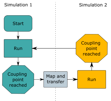
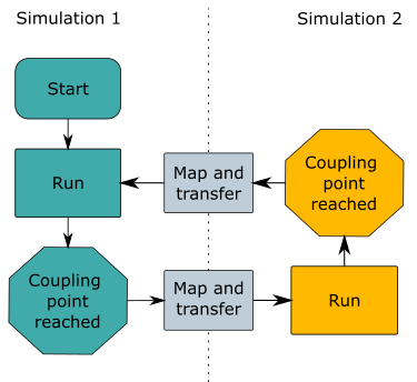
The simulations can be one-way or two-way coupled. In one-way coupled problems, the effect of one of the simulations on the other is neglected. For two-way coupled, each simulation has an impact on the solution of the partner simulation.
| One-Way Coupling | Two-Way Coupling |
|---|---|
 |
 |
Consider, for example, heat transfer between a fluid and a stiff supported structure. The fluid produces thermal deformations in the solid, but these deformations do not necessarily lead to significant changes in the fluid flow. In this case, the thermal interaction is two-way, whereas the mechanical coupling is only one-way. If the structure is loosely supported, the effects of the solid displacements on the fluid flow can also be important. In this case, the mechanical interaction is also two-way.
In a one-way coupled co-simulation, only one of the simulations imports data from the partner simulation. The first simulation runs until it reaches the first coupling point. When the coupling point is met, the solution data is mapped to a local copy of the partner mesh before being transferred to the partner simulation mesh. The second simulation uses the imported data as part of its solution (typically, to set boundary conditions) and runs until the next coupling point. When the coupling point is met, the first simulation runs again, without importing any data from the partner. The process continues until both simulations have satisfied their stopping criteria.
A two-way coupled co-simulation follows the same process, except that both simulations use solution data from the partner: