
本案例利用Fluent计算锥形喷嘴内的流动,并观察喷嘴下游自由空间中的激波钻石(SHOCK DIAMOND)现象。
2 问题描述
案例使用的网格采用ANSYS Meshing生成,如下图所示。
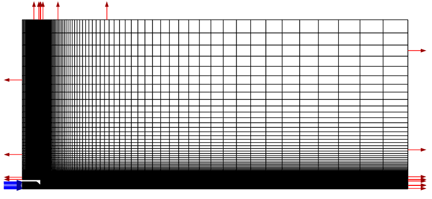
喷嘴局部如图所示。
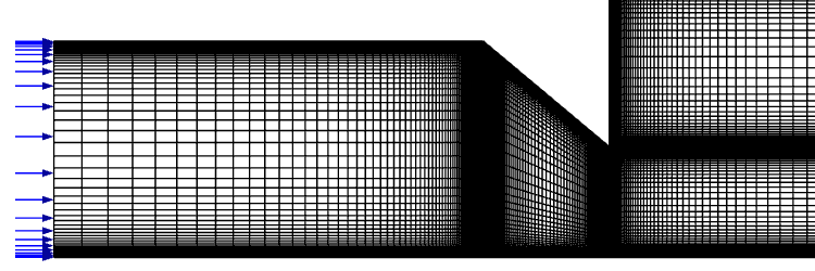
采用压力入口与压力出口边界,其中入口总压为405411.6 Pa,温度277.74 K,出口静压为101352.9 Pa。
3 Fluent设置
3.1 读取网格
-
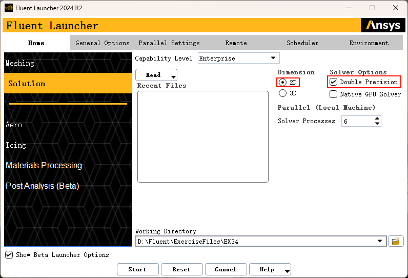
以 2D、Double Precision方式启动Fluent
-
利用菜单 File → Read → Mesh… 读取计算网格文件 conicalnozzle40deg.cas.h5
3.2 General设置
-
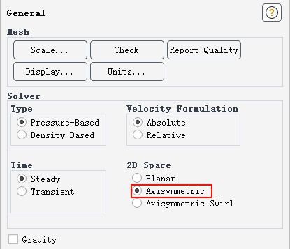
双击模型树节点 General 进入 General任务页,指定2D Space为 Axisymmetric
3.3 设置模型及操作条件
-
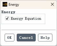
双击模型树节点 Models and Energy (Off) 打开能量方程设置对话框。勾选Energy Equation框,然后选择OK以关闭Energy窗口。
-
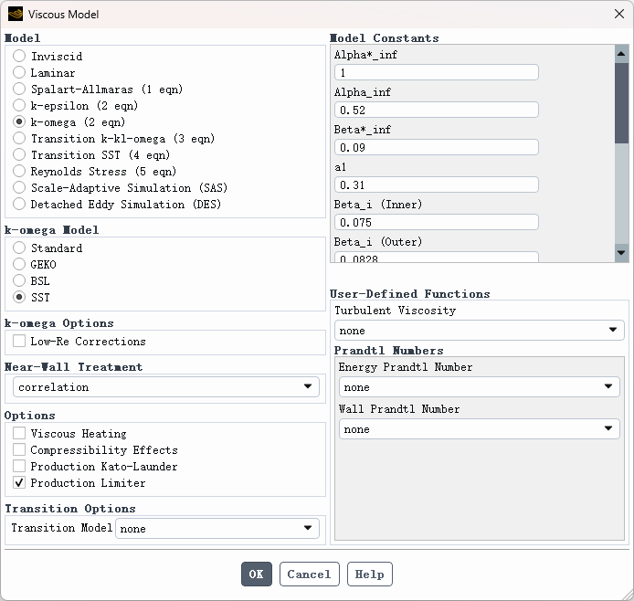
双击模型树节点 Models and Viscous (SST k-omega) 打开湍流模型设置对话框。保持设置如图34.2a所示。点击OK以关闭Viscous Model窗口。
-
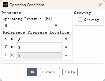
进入功能区 Physics 选项卡,点击按钮 Operating Conditions… 打开操作条件设置对话框。指定 Operating Pressure设置为0。
3.4 指定材料参数
-
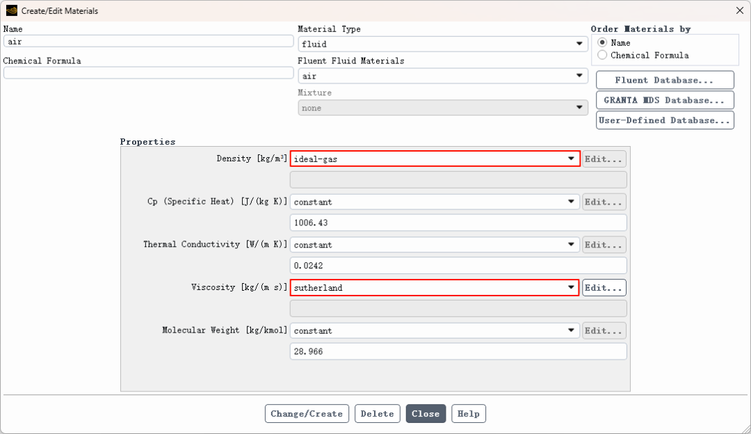
双击模型树节点 Materials > Fluid > air 打开材料属性编辑对话框 -
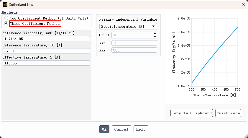
选择ideal-gas作为密度模型,选择sutherland作为粘度模型。
-
选择 Three Coefficient Method 并单击 OK 按钮以关闭Sutherland Law窗口。
-
点击 Change/Create并关闭创建/编辑材料窗口。
3.5 指定边界条件
-
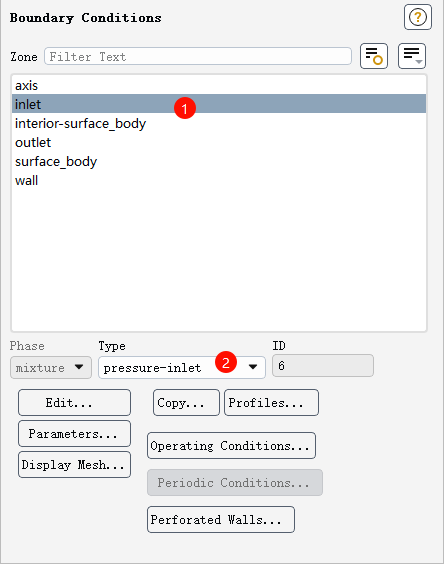
双击模型树节点 Boundary Conditions。 -
在任务页面中选择 inlet ,指定 Type 为 pressure-inlet
-
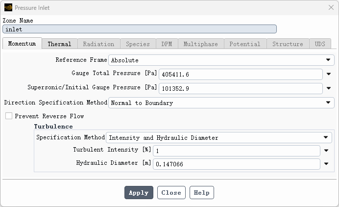
点击 Edit… 按钮打开参数编辑对话框 -
将 Gage Total Pressure [Pa] 设置为 405411.6 -
将 Supersonic/Initial Gauge Pressure [Pa] 设置为 101352.9 -
选择 Turbulence 下的 Specification Method 为 Intensity and Hydraulic Diameter -
将 Turbulence Intensity [%] 设置为 1 -
将 Hydraulic Diameter [m] 设置为 0.147066
-
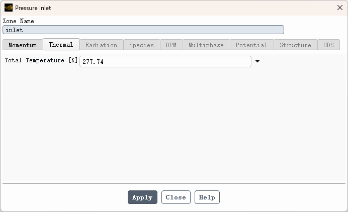
选择 Apply 按钮,然后进入 Thermal 选项卡,将 temperature 设置为 277.74 K。选择 Apply 并关闭压力入口。
-
在任务页面中选择 outlet ,指定 Type 为 pressure-outlet ,点击 Edit… 按钮编辑参数
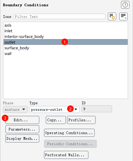
-
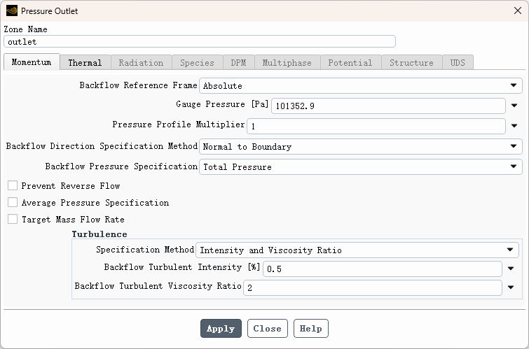
设置以下参数 -
将Gage Pressure [Pa]设置为101352.9 -
在 Turbulence下指定 Specification Method 为 Intensity and Viscosity Ratio -
将Turbulence Intensity [%]设置为0.5 -
将Backflow Turbulent Viscosity Ratio设置为2,见图34.4c。
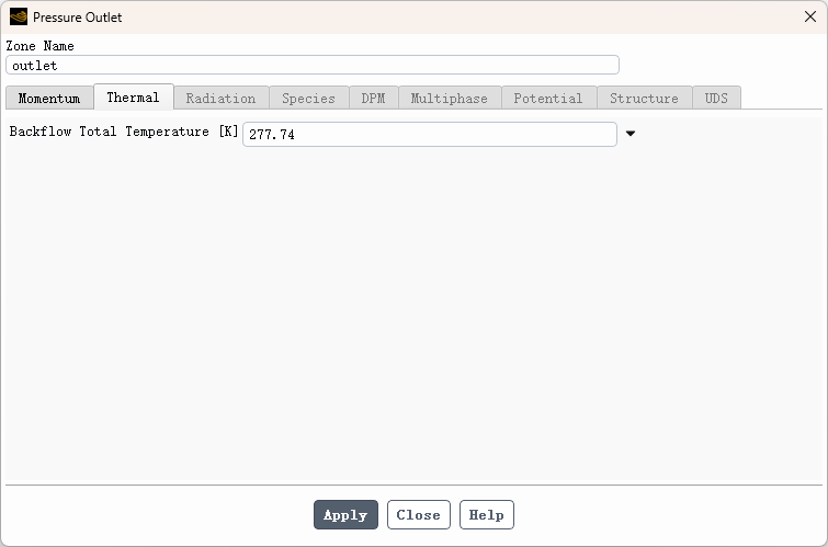
-
选择Apply,然后选择Thermal选项卡,将温度设置为277.74 K。选择Apply和Close以关闭压力入口。
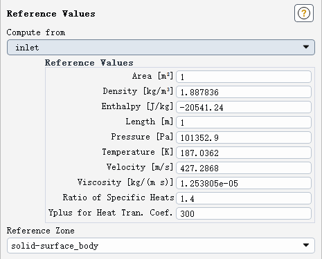
3.6 设置参考值
-
双击节点 Setup > Reference Values 进入Reference Values任务页。 -
在 Compute from 下拉框中选择 Inlet,并选择 solid-surface_body 作为 Reference Zone。
3.7 设置求解算法及控制参数
-
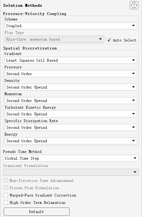
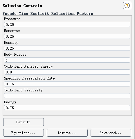
双击Solution下的Methods。保持设置如图34.5a所示。在大纲视图中双击 Solution 下的Controls。选择设置如图34.5b所示。
-
双击 Controls节点,如下图所示设置控制参数
3.8 设置残差监控
-
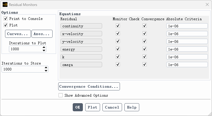
双击模型树节点 Solution > Monitors > Residual打开残差监控设置对话框
3.9 监测出口流量
-
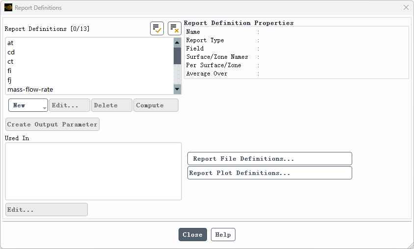
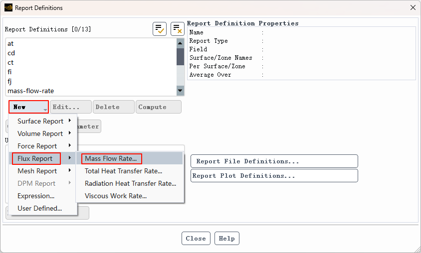
双击模型树中Solution下的Report Definitions节点打开报告定义对话框。
-
选择 New > Flux Report > Mass Flow Rate….
-
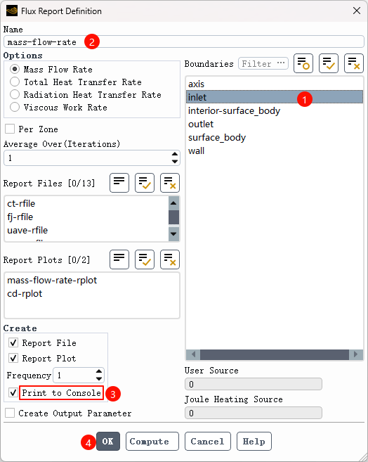
在Flux Report Definition 对话框的 Boundaries列表下选择inlet。 -
输入名称mass-flow-rate。 -
勾选Create下的Print to Console复选框。 -
单击 OK 按钮定义报告
-
关闭报告定义对话框
3.8 初始化并求解
-
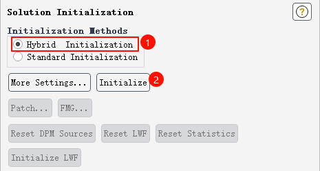
双击模型树节点 Initialization 打开初始化计算任务页,选择 Hybrid Initialization 选项,并点击按钮 Initialize 进行初始化计算
-
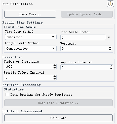
双击节点 Run Calculation 打开计算设置任务页,输入迭代次数 1000,点击按钮 Calculate 开始计算
-
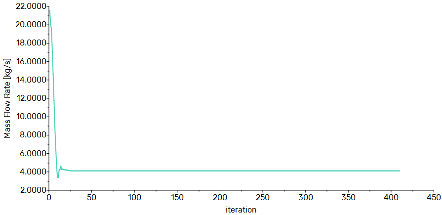
计算中监测的质量流量
4 后处理
-
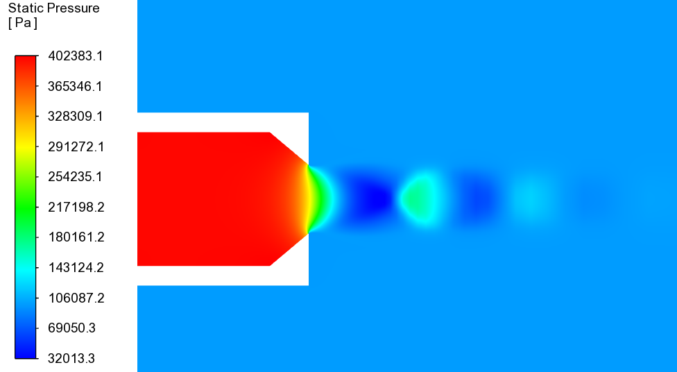
压力分布
-
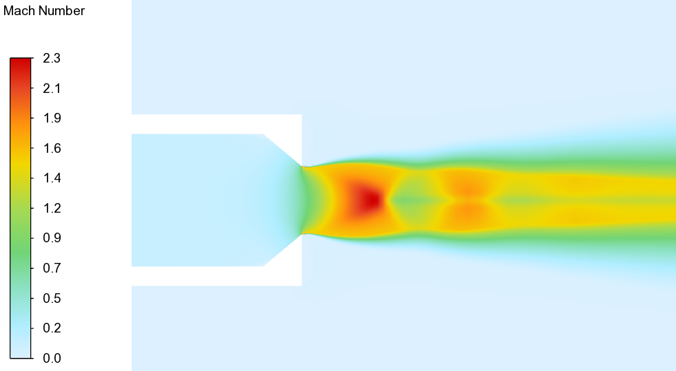
马赫数
-
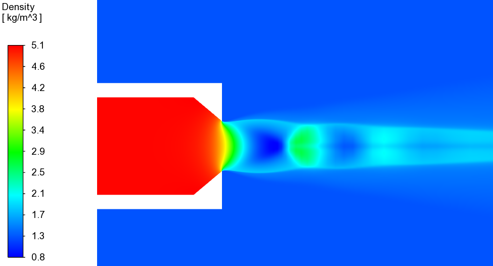
密度
-
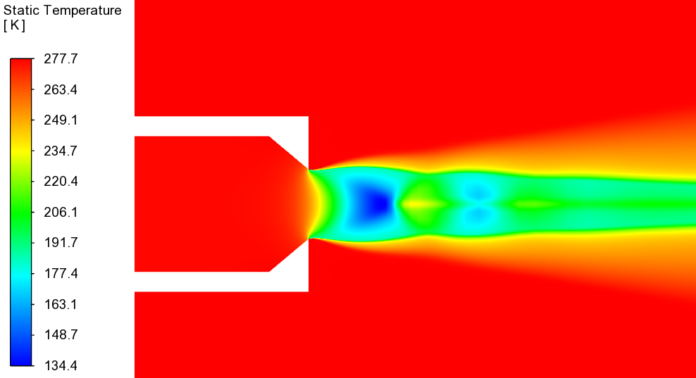
温度
注:本案例计算参数取自网络,计算结果仅作为流程参考,不可用于实际工程。
”
(完)

本篇文章来源于微信公众号: CFD之道


评论前必须登录!
注册