
本案例演示利用 in:Flux 模拟室内通风。
注:本案例为in:Flux自带案例,演示中所需文件均可在其官网下载。
”
1 导入几何并查看
-
启动 in:Flux -
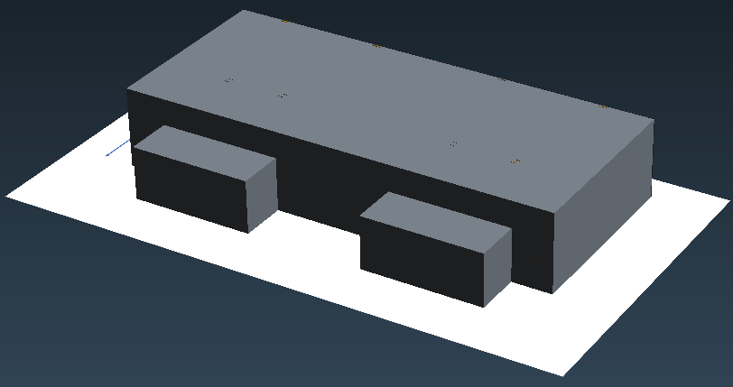
右键选择模型树节点 Import 3D CAD...,打开文件Gas Turbine Enclosure.ifx

导入的几何模型如图所示。
-
在图形窗口点击鼠标右键,选择菜单 Define Clip Plane

-
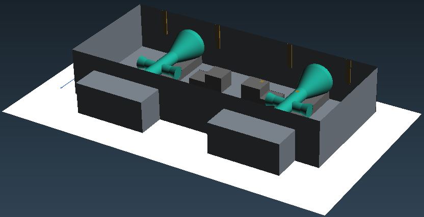
弹出对话框中设置如下图所示参数
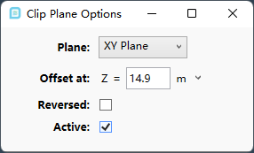
几何模型如下图所示。
2 定义空调入口
-
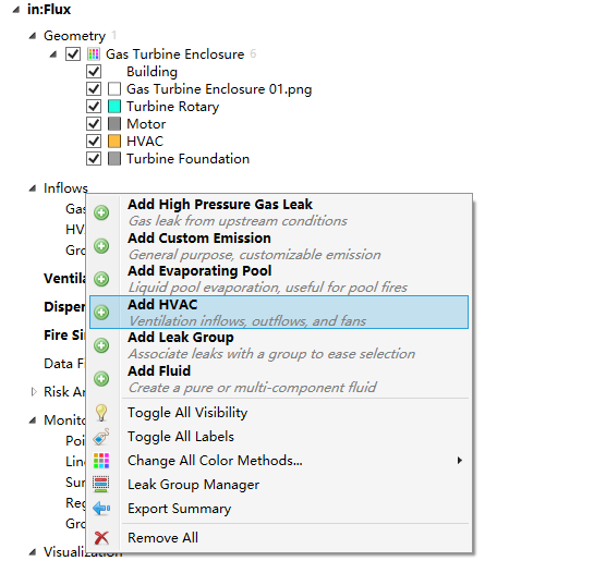
鼠标右键选择节点 Inflows,点击菜单Add HVAC
-
如下图所示添加入口条件
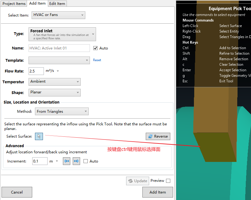
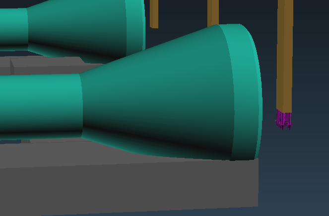
定义完毕后的模型如图所示。注意气流方向。
-
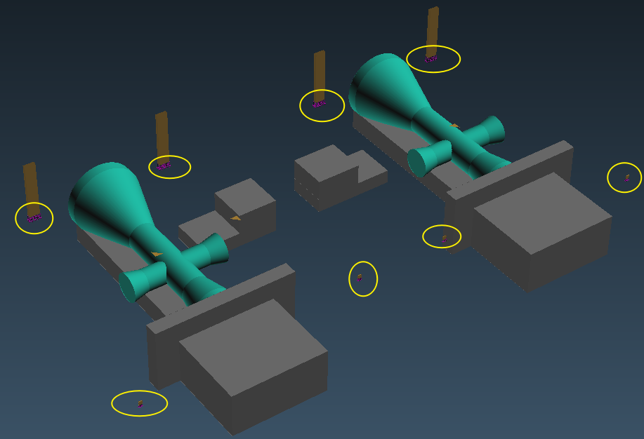
相同的参数定义其他7个空调入口,其位置如下图所示
3 定义出口
-
选择 Type为Forced Outlet ,如下图所示指定出口条件
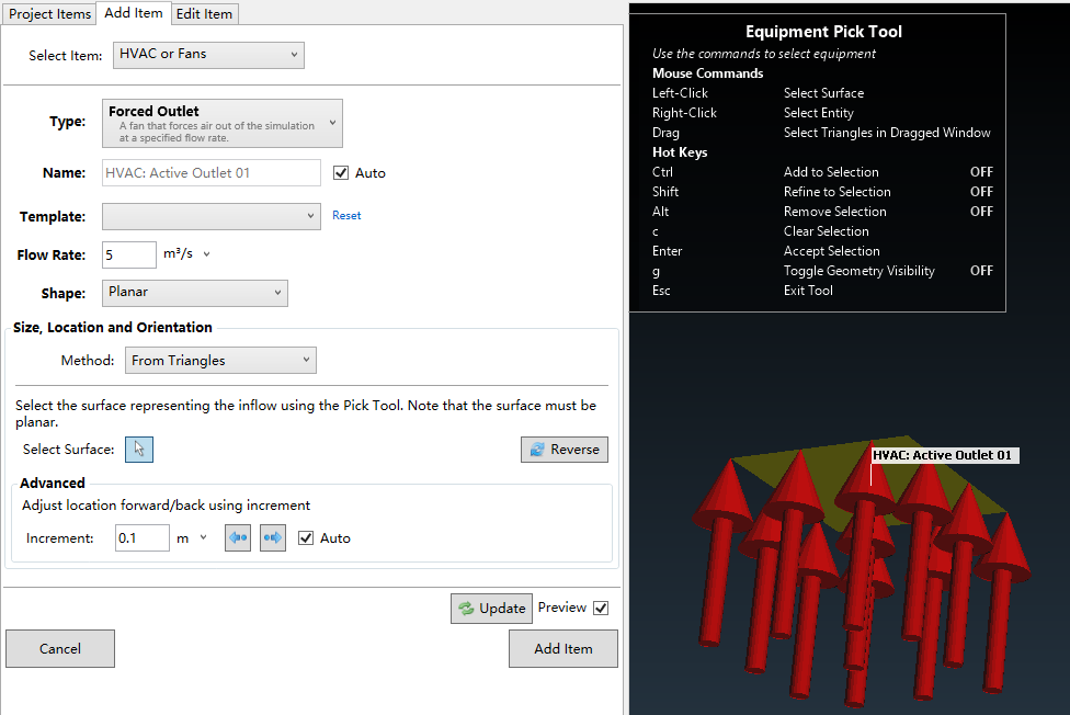
注:这里如果进出口都是流量出口,则需要保证进出口流量相等。
”
-
相同方式定义另外三个出口

4 设置内流场计算
-
添加 Ventilation Simulation,指定Type为Internal,其他参数如下图所示
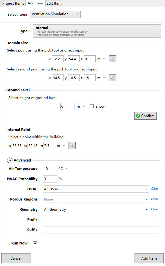
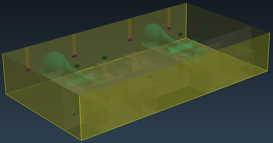
计算区域通过在图形窗口中选择角点来定义。本案例定义的计算区域如下图所示。
5 计算结果
-
定义 z=2 m 平面的空气龄云图
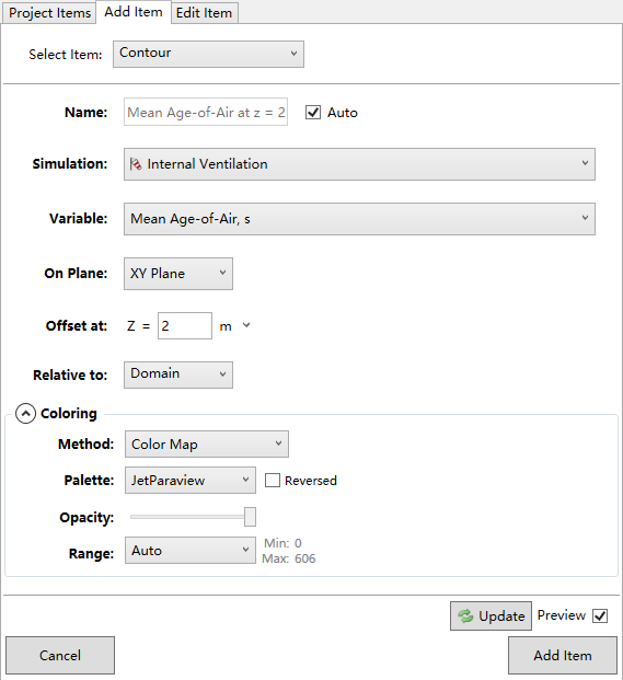
Z=2 m 平面上空气龄分布如下图所示。

in:Flux进行此类的通风计算是真的快出了天际,设置和计算都倍儿块。对于工程中需要进行一些快速决策还是比较好用的。
(完)

本篇文章来源于微信公众号: CFD之道


评论前必须登录!
注册