
该案例演示在STAR-CCM+中求解自然对流问题,并将计算结果与文献数据进行比较验证。
1 问题描述
计算模型如下图所示。内管半径0.0178 m,温度373 K;外管半径0.0463 m,温度327 K。内外管道偏心距0.0178 m。
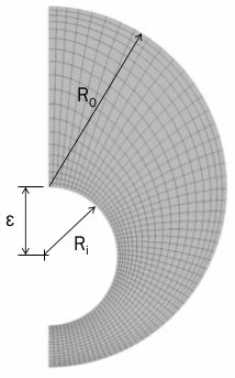
自然对流瑞利数为49500,采用层流模型进行计算。气体密度利用理想气体模型,其他物性参数为常数值。采用二维模型进行计算。
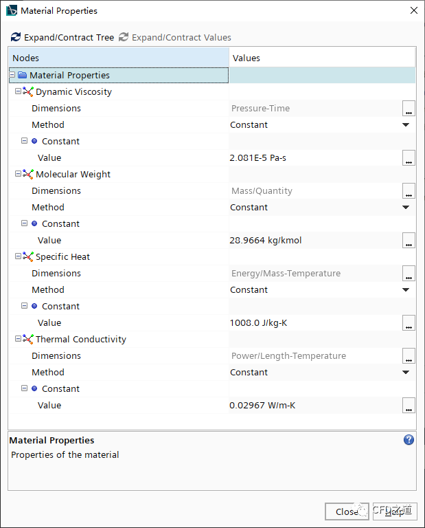
物性参数如下表所示。
| 物性参数 | 参数值 |
|---|---|
| Dynamic Viscosity (Pa-s) | 2.081E-5 |
| Molecular Weight (kg/kmol) | 28.9664 |
| Specific Heat (J/kg-k) | 1008.0 |
| Thermal Conductivity (W/m-K) | 0.02967 |
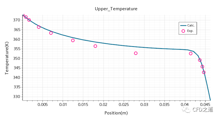
取对称面上的温度值与文献中的试验测量数据进行比较。
2 几何与网格
几何模型在STAR CCM+中直接创建。
-
启动STAR CCM+并利用菜单File → New… 新建Simulation
2.1 创建几何
-
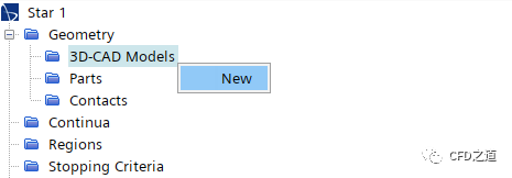
右键选择模型树节点3D-CAD Models,点击弹出菜单项New打开3D-CAD
-
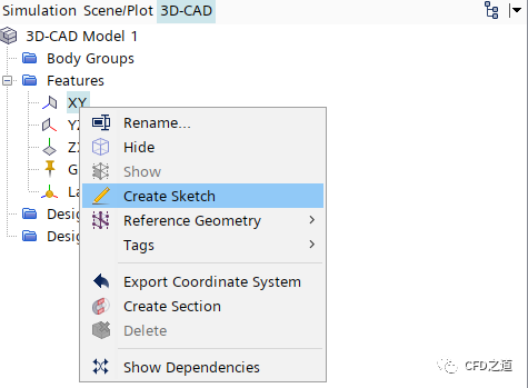
右键选择节点XY,点击弹出菜单项Create Sketch创建草图
-
按下图所示尺寸绘制草图
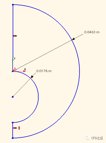
-
右键选择节点Sketch 1,点击弹出菜单项Extrude
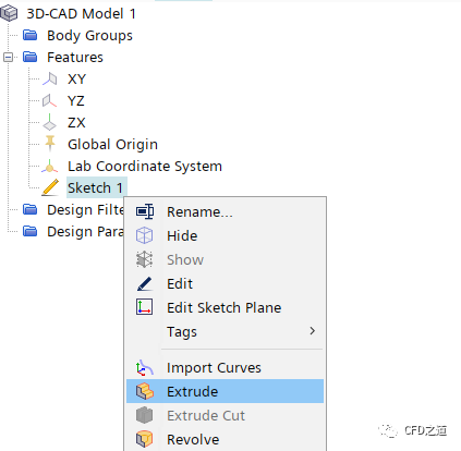
-
如下图所示拉伸0.01 m,点击OK按钮创建三维几何
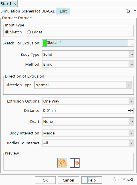
注:这里计算的是2D模型,因此拉伸距离并不重要。
”
-
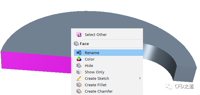
选中下图所示的表面,点击右键菜单Rename,命名为upper
-
相同方式为其他表面命名,如下图所示,命名完毕后关闭3D-CAD面板
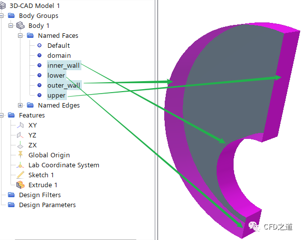
-
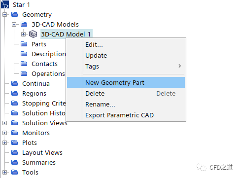
右键选择节点3D-CAD Model 1,点击弹出菜单项New Geometry Part创建部件
2.2 分配区域
-
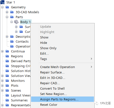
右键选择节点Body 1,点击弹出菜单项Assign Parts to Regions… 打开区域分配对话框
-
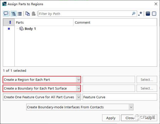
如下图所示选择选项,并点击Apply按钮创建区域
-
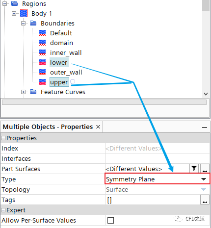
如下图所示,指定边界lower及upper的类型为Symmetry Plane
2.3 划分网格
-
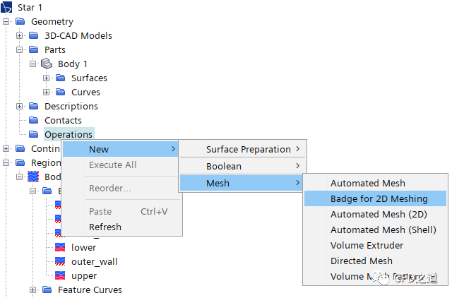
右键选择模型树节点Operations,点击弹出菜单项New → Mesh → Badge for 2D Meshing
-
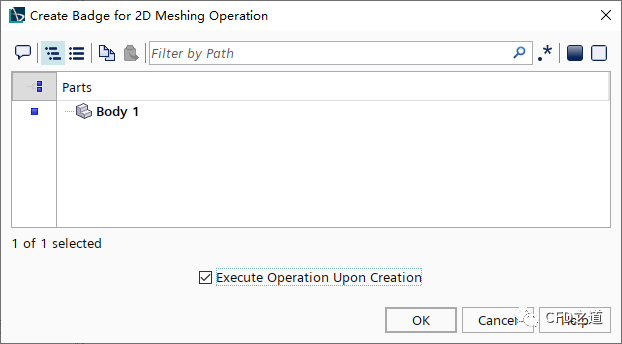
弹出对话框中选择Body 1,激活选项Execute Operation Upon Creation,点击OK按钮关闭对话框
-
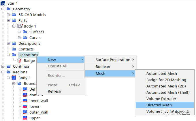
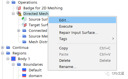
右键选择节点Operations,点击弹出菜单项New → Mesh → Directed Mesh
-
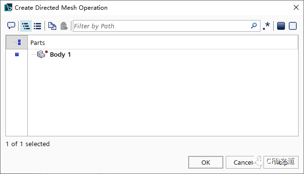
弹出对话框中选择Body 1,点击OK按钮关闭对话框
-
右键选择节点Directed Mesh,点击弹出菜单项Edit… 打开设置面板
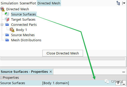
-
如下图所示指定Source Surfaces为domain
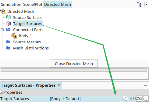
-
如下图所示指定Target Surfaces为Default
-
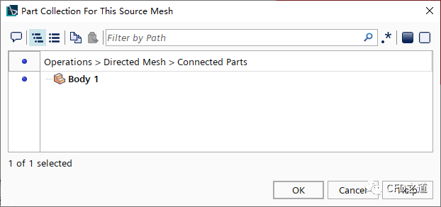
右键选择节点Source Meshes,点击弹出菜单项New Source Mesh → Patch Mesh
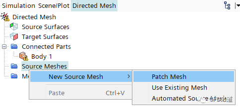
-
弹出对话框中选择Body 1,点击OK按钮关闭对话框并打开新的面板
-
点击下图所示按钮,软件自动识别映射边界
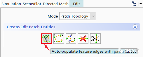
-
设置Mode为Patch Mesh,选中图中所示高亮的几何边,如下图所示指定参数,并点击Apply按钮
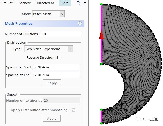
-
选中图中所示高亮的几何边,如下图所示指定参数,并点击Apply按钮
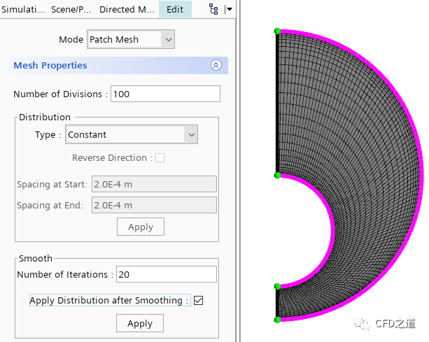
-
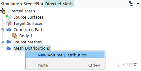
右键选择节点Mesh Distributions,点击菜单项New Volume Distribution
-
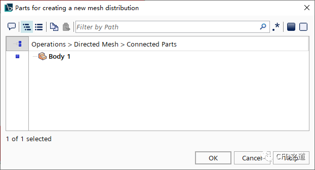
选择Body 1
-
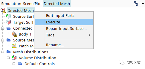
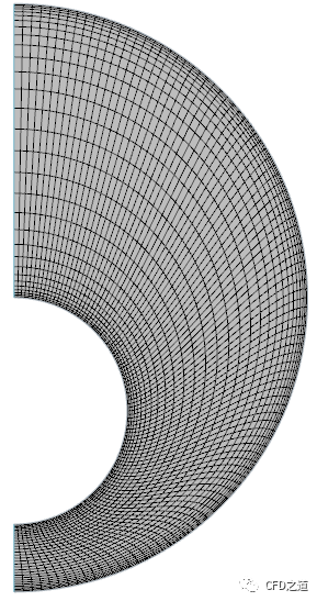
右键选择节点Directed Mesh,点击弹出菜单项Execute生成网格
生成的网格如下图所示。
3 选择物理模型
-
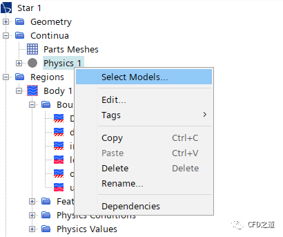
右键下载模型树节点Physics 1 ,点击弹出菜单项Select Models… 打开模型选择对话框
-
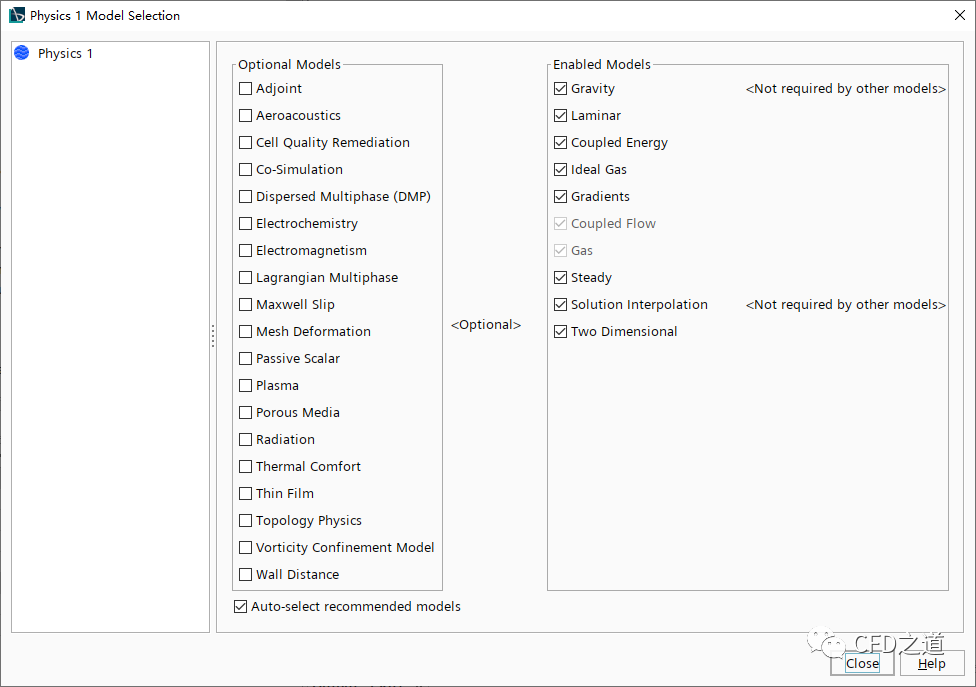
选择以下物理模型 -
Two Dimensional -
Steady -
Gas -
Coupled Flow -
Ideal Gas -
Laminar -
Gravity
选择完毕后的对话框如下图所示。
4 设置材料物性
-
双击模型树节点Physics 1 > Models > Gas > Air > Material Properties,弹出材料属性设置对话框,如下图所示设置参数
5 设置初始条件
-
双击节点Physics 1 > Initial Conditions,如下图设置初始条件
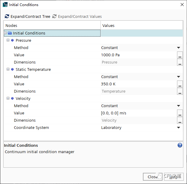
注:对于稳态计算来说,初始值对最终结果没有影响,但会影响收敛过程。
”
6 设置边界条件
-
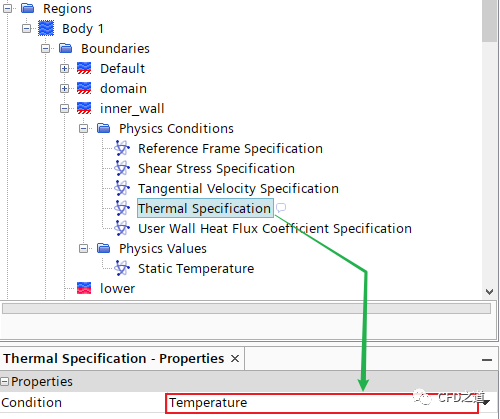
选中模型树 节点Body 1 > Boundaries > inner_wall > Physics Conditions > Thermal Specification,指定Condition为Temperature
-
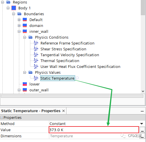
选中节点Physics Values > Static Temperature,指定温度值为373 K
-
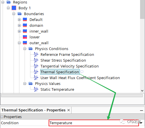
选中模型树 节点Body 1 > Boundaries > outer_wall > Physics Conditions > Thermal Specification,指定Condition为Temperature
-
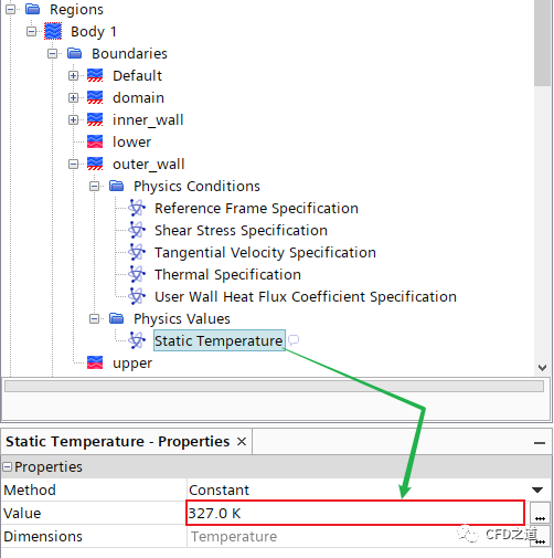
选中节点outer_wall > Physics Values > Static Temperature,指定温度值为327 K
7 收敛监控
添加残差标准用于控制收敛。
-
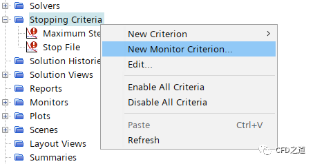
右键选择模型树节点Stopping Criteria,点击弹出菜单项New Monitor Criterion…
-
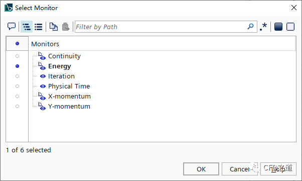
弹出的对话框中选择Energy,点击OK按钮添加能量方程残差
-
相同方式添加Continuity、X-momentum及Y-momentum -
如下图所示选择新添加的4个节点,设置选项 Logical Rule为And
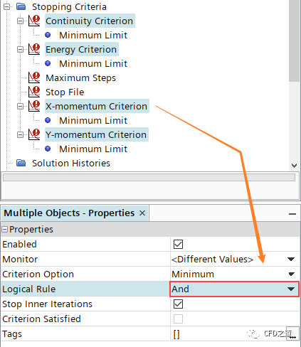
注:设置为And表示需要同时满足设定条件,才能被判断为计算收敛。
”
-
选中节点Energy Criterion > Minimum Limit,指定 Minimum Value为1e-6
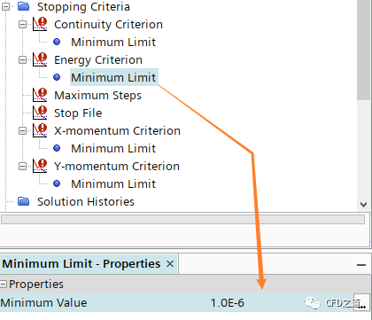
注:能量方程收敛残差至少应当保证低于1E-6
”
8 绘制曲线
-
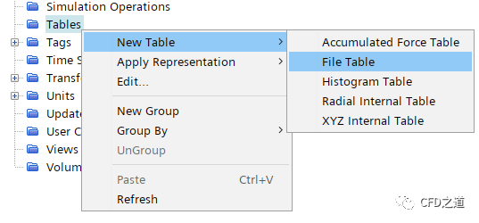
右键选择模型树节点Tools > Tables,点击弹出菜单项New Table → File Table
-
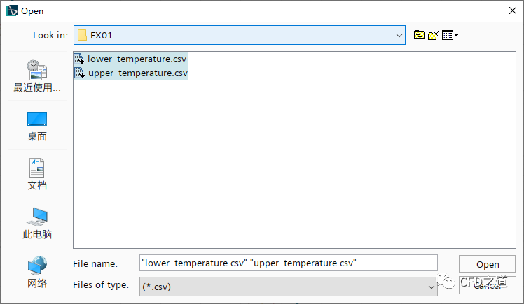
文件选择对话框中添加数据文件,如下图所示
-
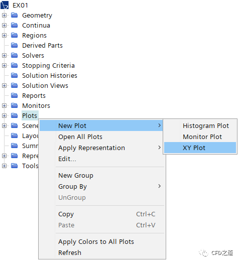
右键选择模型树节点Plot,点击弹出菜单项New Plot → XY Plot新建绘图,修改节点名称为upper
-
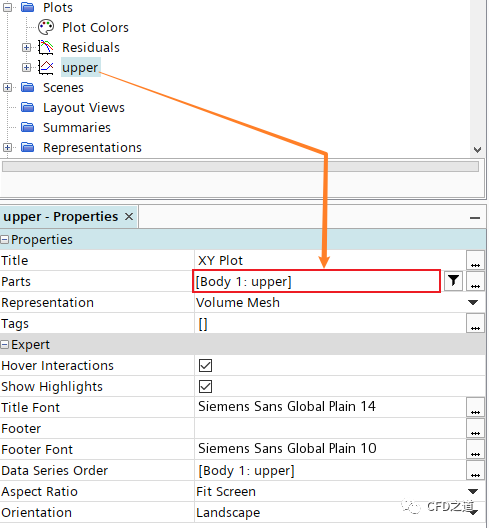
选中节点upper,指定 Parts为upper
-
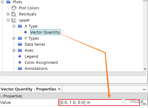
指定X Type > Vector Quantity 为 [0,1,0] ,表示沿Y坐标分布
-
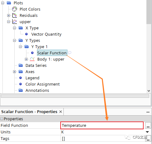
设置Y轴变量为Temperature,如下图所示
-
选中节点Body 1:upper,激活选项Sort Plot Data
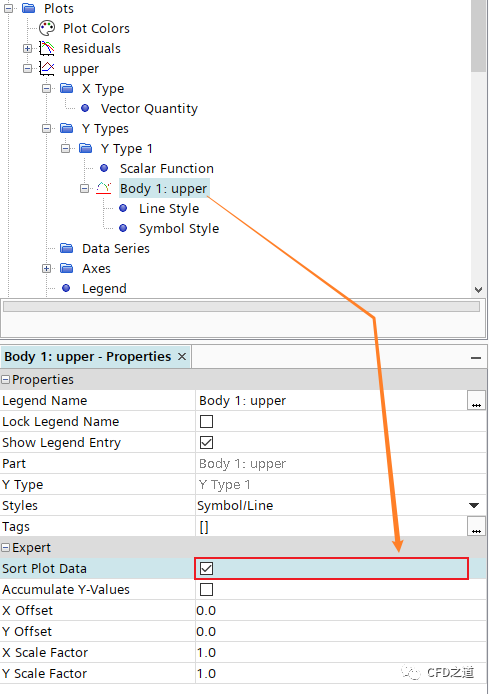
注:若不激活此选项,则以线条显示曲线时会混乱。
”
-
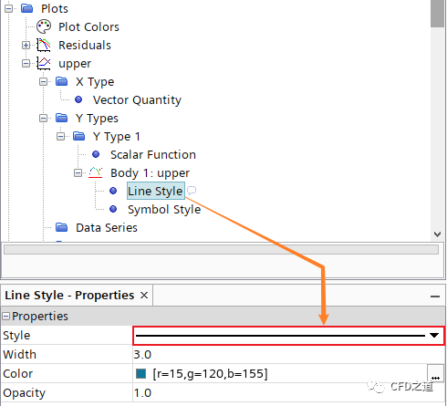
设置Line Style为实线,如下图所示
-
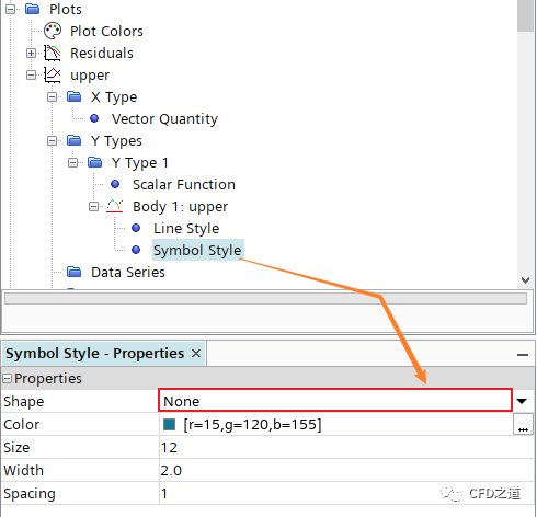
如下图所示,指定Symbol Style为None,表示不显示标记点
-
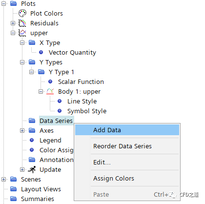
右键选择节点Data Series,点击弹出菜单项Add Data
-
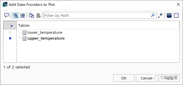
添加数据upper_termperature,点击OK按钮添加数据
-
相同方式绘制边界lower上的温度随Y坐标分布,并添加试验数据lower_temperature -
创建Scalar Scene,指定显示变量为Temperature
9 求解计算
-
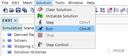
点击菜单Solution → Run开始计算
10 计算结果
-
温度分布
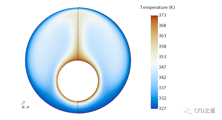
注:这里的云图显示是经过了镜像处理后的结果。
”
-
上对称面的温度分布计算值与试验值比较
-
下对称面的温度分布计算值与试验值比较
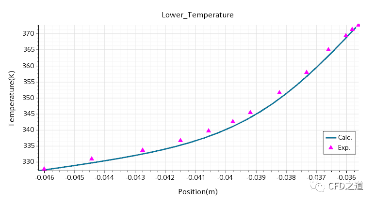
文中的参照数据取自文献:
[1]Cho, C., Chang, K. & Park, K., 1982. Numerical Simulation of Natural Convection in Concentric and Eccentric Horizontal Cylindrical Annuli. ASME. J. Heat Transfer, 104(4), pp. 624-630.
[2]Kuehn, T. H. and Goldstein, R. J. An experimental study of natural convection heat transfer in concentric and eccentric horizontal cylindrical annuli. J. Heat Trans. (100) pp. 635-640, 1978.”
相关文件:
链接:https://pan.baidu.com/s/1pkiy5c7k2w5RTkl7mcA4wQ 提取码:h5do
”
(案例完毕)

本篇文章来源于微信公众号: CFD之道


评论前必须登录!
注册