
本文描述在Fluent Meshing中利用watertight geometry工作流处理计算区域中包含有无厚度挡板的几何模型。
挡板通常指的是出现在计算区域中的非常薄的固体区域,在进行CFD计算的过程中,挡板可能起到的作用包括影响流速与压力、传热或发生壁面化学反应等。挡板壁厚相对于其面积来讲非常小,若想要在计算中保留完整的固体区域,则势必要采用非常小的网格尺寸才能够捕捉到几何,这可能导致计算网格数量急剧增加。因此在实际应用过程中,常将挡板简化为无厚度壁面,在计算时根据具体情况决定是否考虑输入挡板的壁厚。
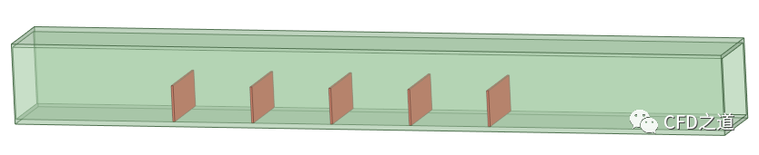
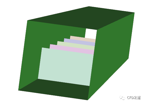
如下图所示的矩形通道内包含有5个挡板。
-
利用SCDM中的抽取中面功能将挡板转化为无厚度壁面
-
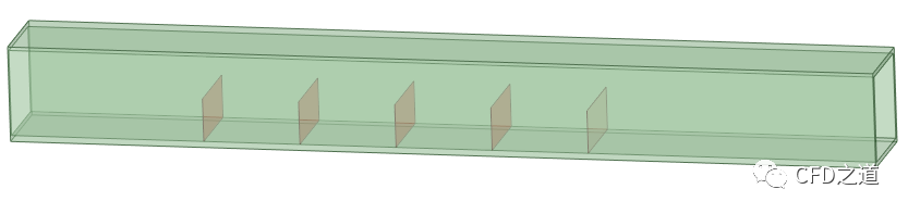
中面抽取完毕后将挡板的固体实体删除掉,同时抽取流体域。流体域抽取完毕后将通道固体删除掉,保留挡板与流体域,如下图所示。
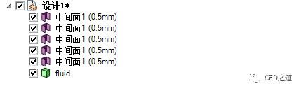
此时模型树节点如下图所示。
-
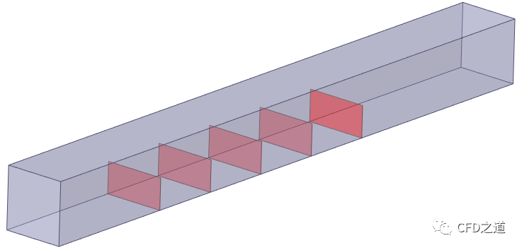
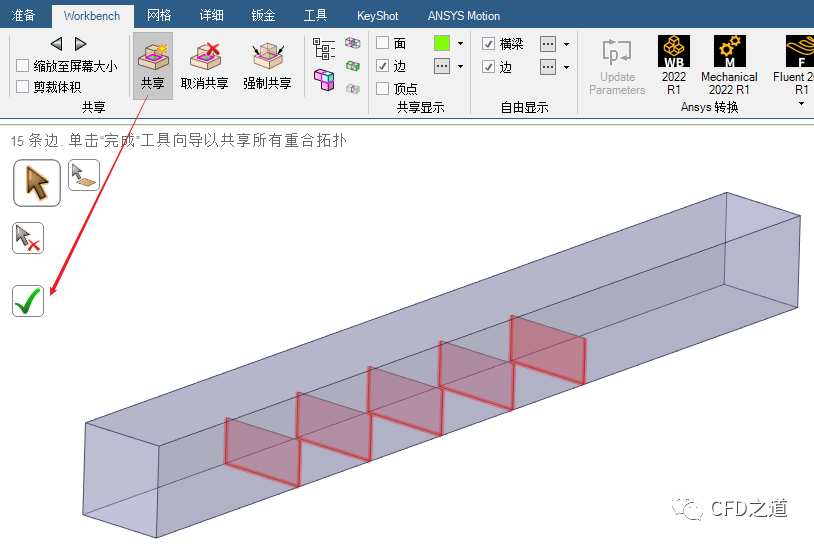
创建共享拓扑。
-
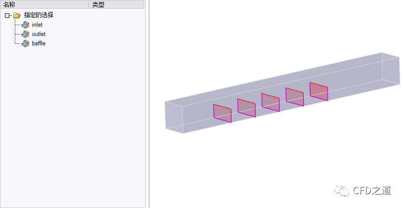
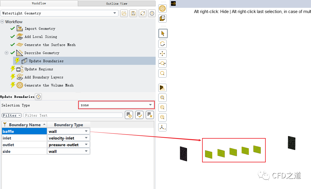
给计算域边界及挡板命名。
注:这里给挡板命名貌似没什么用,在Fluent Meshing中依然识别不了。
”
进入Fluent Meshing。
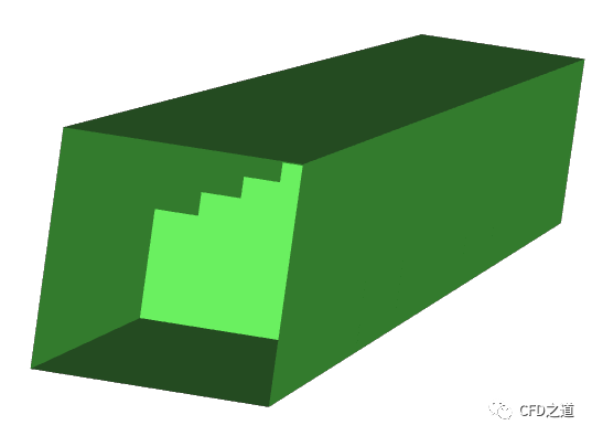
导入几何后会发现挡板壁面被导入了,但是并未分离开。这里需要手工对其分割。
-
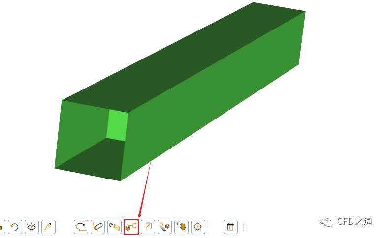
图形窗口中选中挡板面,点击工具按钮Separate将分割表面
分割完毕后如下图所示。可以看到所有的挡板与侧壁面分割开了,颜色不一样。
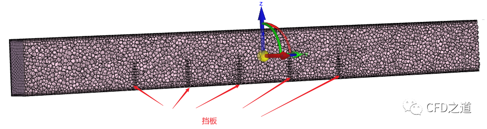
按常规方式生成网格。
生成网格后,可以看到挡板附近存在边界层网格。
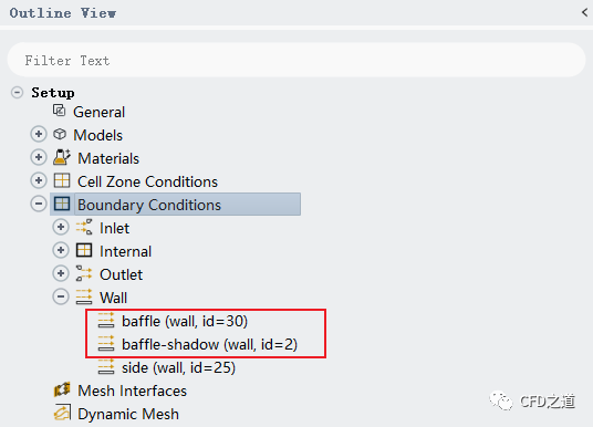
进入Fluent,检查边界,可以看到挡板边界自动生成了shadow面。
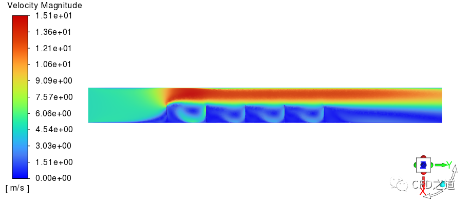
给入口一个速度,计算完毕后查看速度分布,可以看到挡板起到作用了。
文中的相关文件:
链接:https://pan.baidu.com/s/1ACWQrmnYJeRLbLMq73OBmw?pwd=itub 提取码:itub
”
(完毕)

本篇文章来源于微信公众号: CFD之道


流沙老师 我想让这个壁面为一层软的薄膜材料 它随气体的流动而运动 该如何设置?并且能够看到这个薄膜材料在流动气体中的变形 需要注意哪些方面 希望老师能给些指导
想要看变形,就得把几何建出来
您的意思是需要把三维模型建出来 不能用壳体代替 对吗?但是种薄膜材料的厚度只有0.15mm 那网格将会非常多吧(~_~