
本案例演示在Fluent Meshing中利用Watertight Geometry流程生成interface边界的过程。
注意,本案例仅为演示。在较新的Fluent版本中,Interface的用处越来越小。大多数情况下,建议对几何进行共享拓扑处理以生成共节点的计算网格。不过在一些特殊的场合下,如使用滑移网格时,还是需要生成Interface。
早期的版本中,Fluent Meshing的Watertight Geometry工作流无法生成Interface,在2022R2版本中,Fluent Meshing的Watertight Geometry工作流中可以生成Interface。
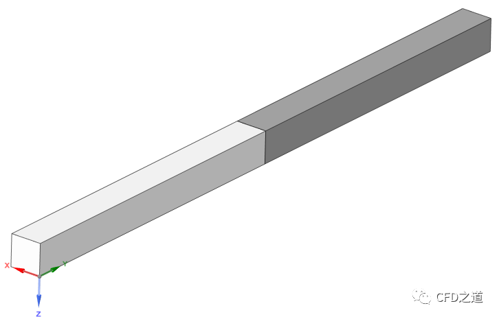
演示模型如下图所示。注意几何处理做完后,不要进行共享拓扑。
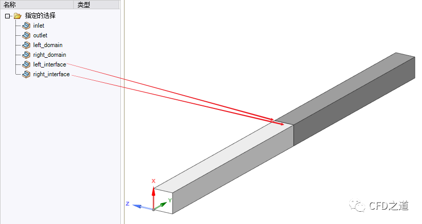
边界、区域命名和常规处理一样,可以给interface面命名,方便后期识别,如下图所示。
进入Fluent Meshing中采用Watertight Geometry流程进行网格划分。
-
在 Describe Geometry任务页中,如下图所示,选择Non-Coformal Mesh between objects为Yes ,此时软件会自动设置参数Do you want to apply Share Topology为No
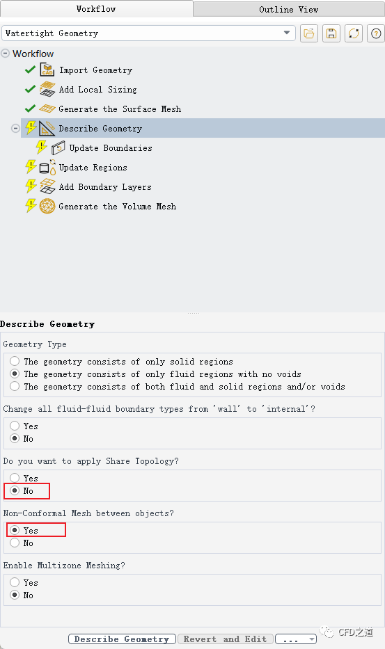
注:此选项是Fluent 2022R2版本才有的。
”
-
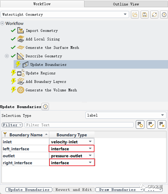
进入 Update Boudaries任务页中,如下图所示,设置两个交界面的边界类型为interface
其他所有设置与常规设置一样。生成网格并切换到Solution模式。
-
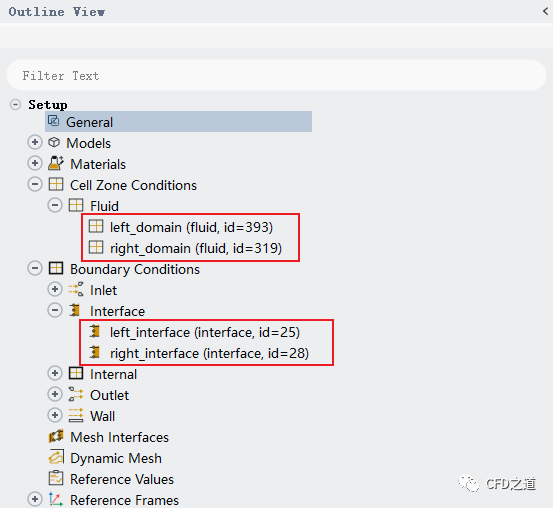
可以看到有两个区域,且边界条件中有两个interface边界
-
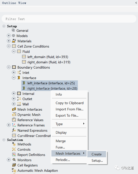
如下图所示,选中两个interface节点,点击鼠标右键菜单项 Mesh Interfaces → Create创建interface对
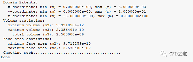
此时点击General面板中的Check按钮查看网格,如下图所示可以看到网格没有问题了。
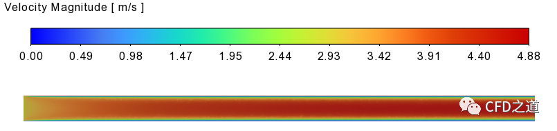
设置入口速度3 m/s进行计算,计算结果如下图所示,可以看到两个计算区域是连通的。
(完)

本篇文章来源于微信公众号: CFD之道


评论前必须登录!
注册