
案例演示利用STAR CCM+计算聚合物熔体液膜铸造过程。
1 问题描述
在工业中,液膜铸造是生产薄聚合物薄膜的常用方法。薄膜通常用于食品和纺织包装、弹力包装或塑料袋等应用场景。STAR-CCM+ 提供的液膜铸造模型和自由表面模型可对该过程进行模拟,并研究各种参数对生成的薄膜的影响。
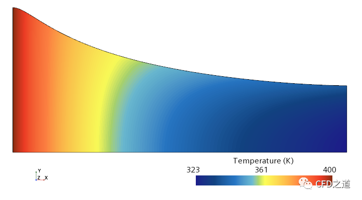
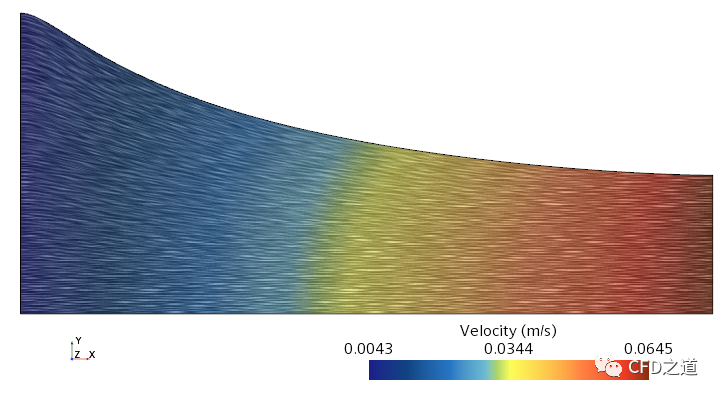
在液膜铸造过程中,聚合物熔体穿过扁平狭缝模拉伸到冷却辊上,并在辊子上快速冷却。冷却辊的速度高于模具出口处的熔体速度。此速度比称为拉伸比,导致聚合物在拉伸流中被拉伸和定向。材料介质属性和液膜铸造工艺条件对液膜形成有显著影响。
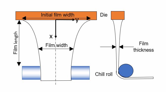
该图显示聚合物膜如何在由于质量守恒而退模后在宽度(缩口)和厚度方面减小。液膜铸造工艺取决于影响液膜形成的多个参数,包括:
-
初始膜宽度:0.2 m -
模具出口处的液膜厚度:0.46 mm -
液膜长度 - 模具出口和液膜与冷却辊之间接触点之间的距离:0.23 m -
拉伸比 - 定义为冷却辊上的液膜速度与模具出口处的速度之比:
本教程演示如何在 STAR-CCM+ 中对聚合物熔体的液膜铸造拉伸建模。您创建的几何体和网格仅对液膜自身进行建模。模具和冷却辊不计入几何,但其影响作为边界条件应用。计算网格为二维,并描述膜的宽度和长度。网格的最初形状是矩形,宽度为初始膜宽度。沿拉伸方向的膜宽度变化由自由表面模型计算得出。在稳态模拟过程中,网格根据预测的膜宽度使用变形器进行变形。液膜厚度不由网格解析,但通过液膜铸造模型作为标量计算,您可以分析其在二维网格上的分布状况。由于工艺配置基于中心线对称,因此只需对几何体的一半建模。
2 几何建模
-
启动STAR CCM+ 2021.2并新建Simulation -
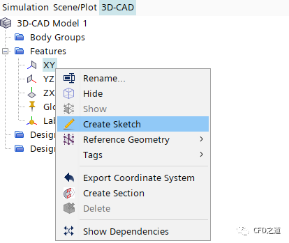
鼠标右键点击模型树节点Geometry > 3D-CAD Models,选择弹出菜单项New进入3D-CAD模式 -
鼠标右键选择模型树节点XY,点击弹出菜单项Create Sketch创建草图
-
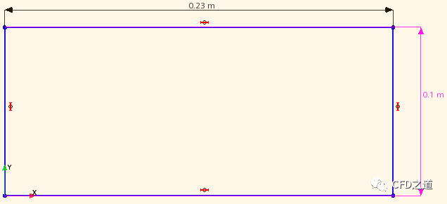
创建如下图所示尺寸的草图
-
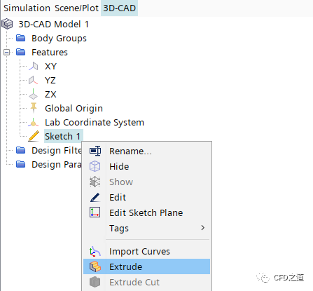
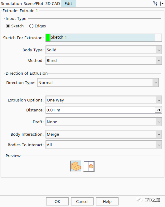
右键选择节点Sketch 1,点击菜单项Extrude
-
采用默认参数进行拉伸
3 创建参数
-
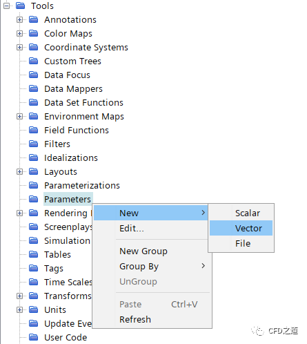
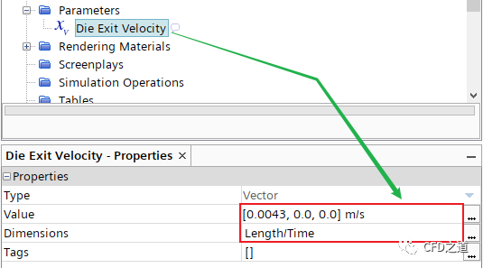
右键选择模型树节点Tools > Parameters,点击弹出菜单项New → Vector创建新的节点,修改节点名称为Die Exit Velocity
-
定义向量的值为[0.0043, 0, 0] ,指定其量纲为Length/Time
-
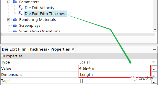
创建另一个Scalar参数,命名为 Die Exit Film Thickness,按下图所示进行参数指定
-
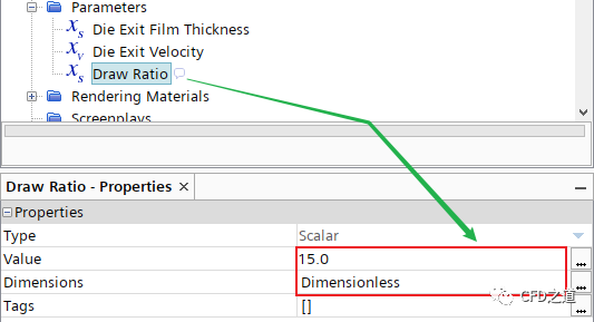
创建一个无量纲scalar参数,命名为Draw Ratio,按下图所示进行参数指定
4 创建初始薄膜网格
-
鼠标右键选择模型树节点Geometry > 3D-CAD Models > 3D-CAD Model 1,点击弹出菜单项New Geometry Part,弹出对话框中采用默认参数,将几何转化为零部件 -
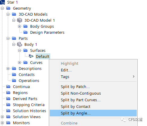
右键选择模型树节点Parts > Body 1 > Surfaces > Default,点击弹出菜单项Split by Angle… 分割几何面
-
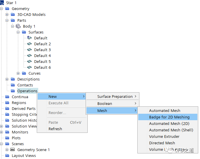
右键选择模型树节点Operations,点击弹出菜单项New → Mesh → Badge for 2D Meshing
-
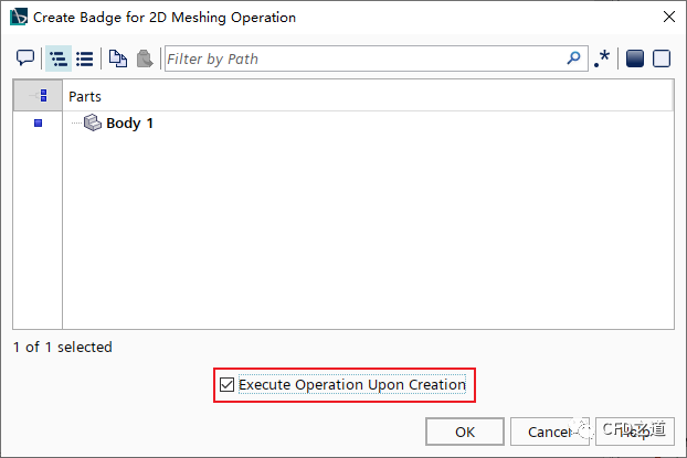
弹出的对话框中选择Body 1部件,并激活选项Execute Operation Upon Creation,点击OK按钮关闭对话框
-
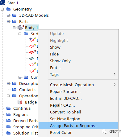
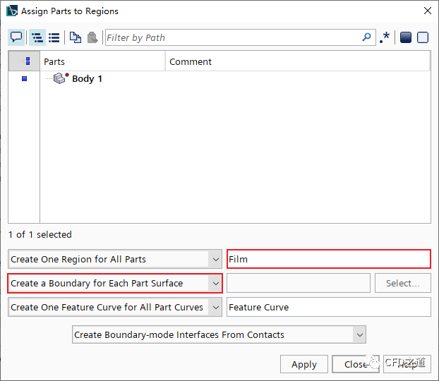
右键选择模型树节点Parts > Body 1,点击弹出菜单项Assign Parts to Regions…
-
弹出对话框中采用下图所示设置,依次点击Apply及Close按钮确认并关闭对话框
-
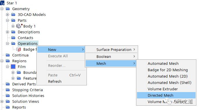
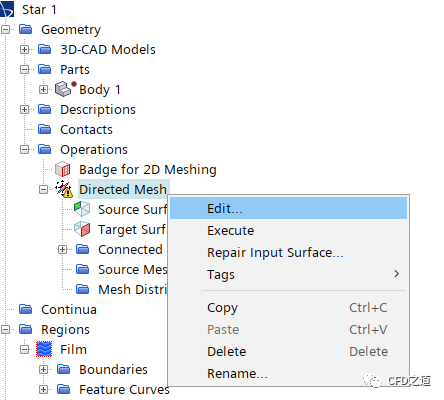
右键选择模型树节点Operations,点击弹出菜单New → Mesh → Directed Mesh
-
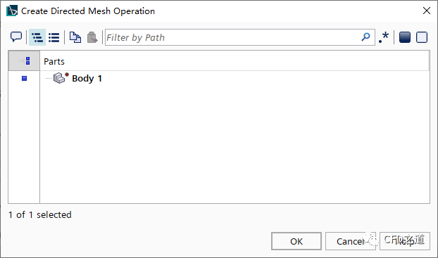
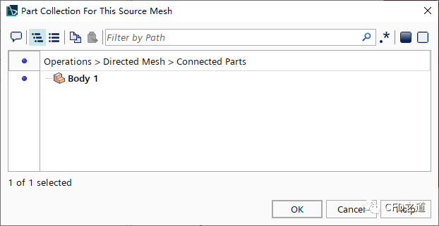
弹出对话框中选择几何部件Body 1,点击OK按钮关闭对话框
-
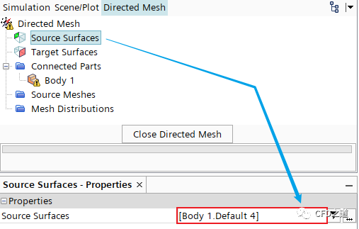
右键选择节点Directed Mesh,点击弹出菜单项Edit… 打开网格设置面板
-
在网格设置面板中,指定 Source Surfaces为Body 1.Default 4
-
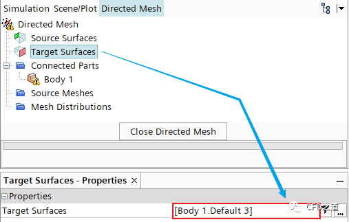
指定 Target Surfaces为Body 1.Default 3
-
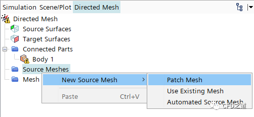
右键点击节点Source Meshes,选择菜单项New Source Mesh → Patch Mesh
-
弹出对话框中选择Body 1,点击OK按钮关闭对话框
-
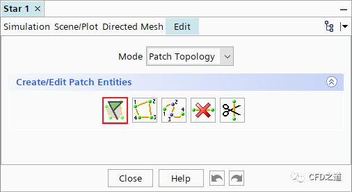
在设置面板中点击按钮Auto-populate feature edges with patch curves
-
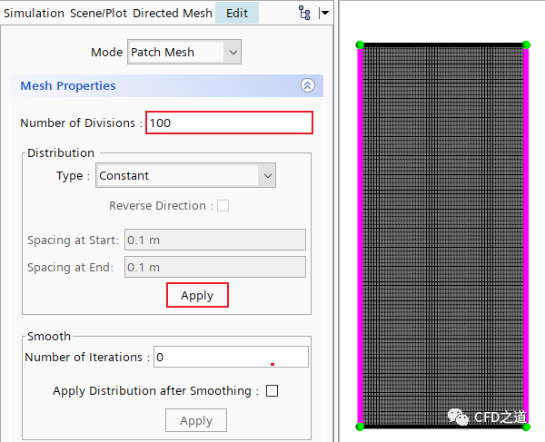
设置 Mode为Patch Mesh,如下图所示指定两个长边,设置Number of Divisions为100,点击Apply按钮确认
-
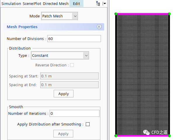
相同方式指定短边网格数量为60
-
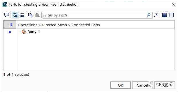
右键选择节点Mesh Distributions,点击菜单项New Volume Distribution
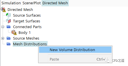
-
弹出对话框中选择Body 1,点击OK按钮关闭对话框
-
右键选择模型树节点Directed Mesh,点击菜单项Execute生成计算网格
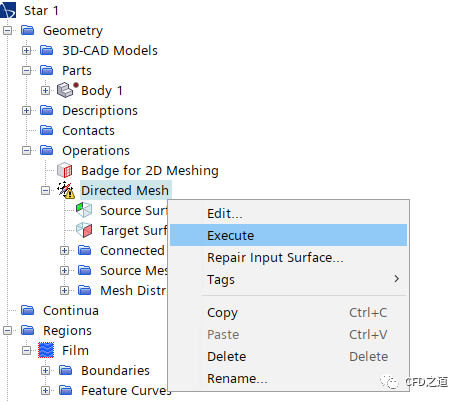
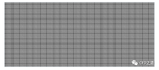
计算网格如下图所示。
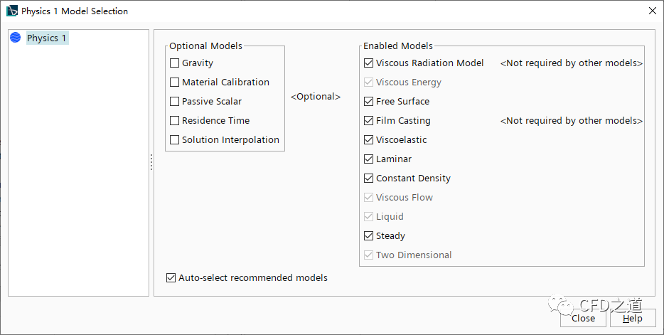
5 选择物理模型
-
右键选择模型树节点Physics 1,点击菜单项Select Models… 打开模型选择对话框

-
选择以下物理模型 -
Two Dimensional -
Steady -
Liquid -
Viscous Flow -
Viscoelastic -
Film Casting -
Viscous Energy -
Viscous Radiation Model
模型选择完毕后如下图所示。
-
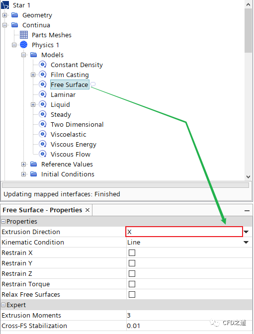
选中模型树节点Models > Free Surface,设置 Extrusion Direction为X
-
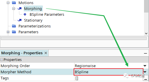
选中模型树节点Tools > Motions > Morphing,指定 Morpher Method为BSpline
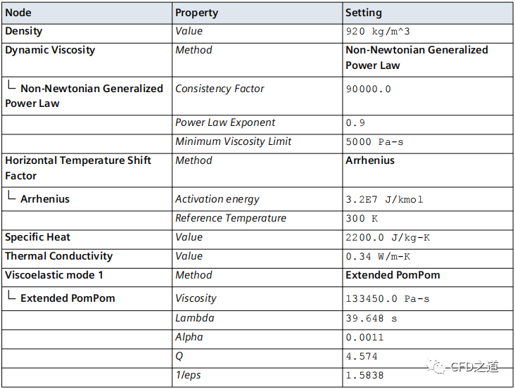
6 指定材料参数
-
修改节点Physics 1 > Models > Liquid > H2O名称为Polymer -
进入节点Polymer > Material Properties,按下表参数进行设置
7 设置液膜边界条件
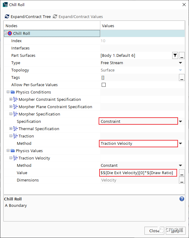
薄膜从模具出口以0.0043 m/s的速度进入计算域。初始时刻薄膜厚度为0.46 mm,温度为400 K。薄膜通过受约束的自由流边界被拉出区域,牵引速度为:
式中,为模具出口速度,为拉伸比。
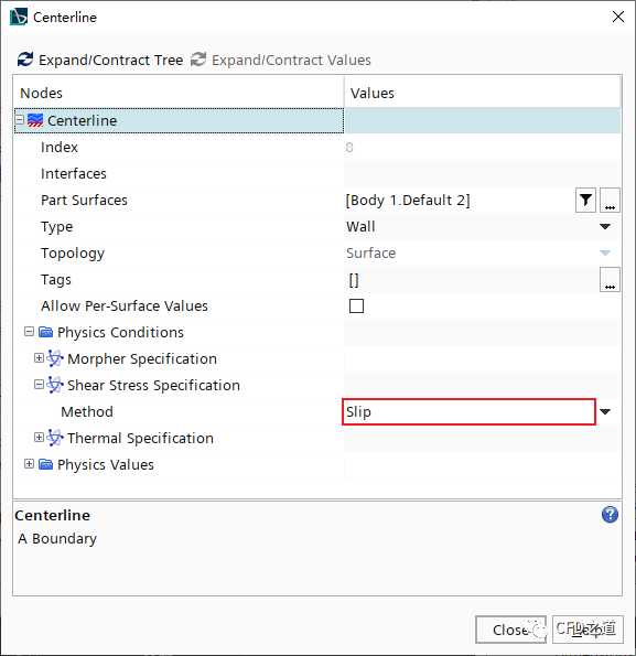
由于假定薄膜是对称的,因此案例中只模拟了一半宽度。在中心线位置应用滑动壁面边界条件;薄膜的侧面为自由表面。自由表面的形状由自由流位移边界建模,该边界根据计算的膜宽度移动。
-
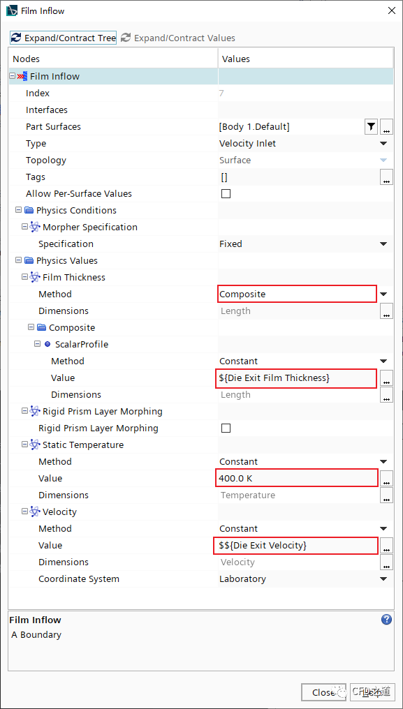
Regions > Film > Boundaries > Body 1.Default,修改其名称为Film Inflow,并指定其类型为Velocity Inlet -
鼠标双击节点Film Inflow,如下图所示设置边界参数
-
修改边界Body 1.Default 2名称为Centerline
-
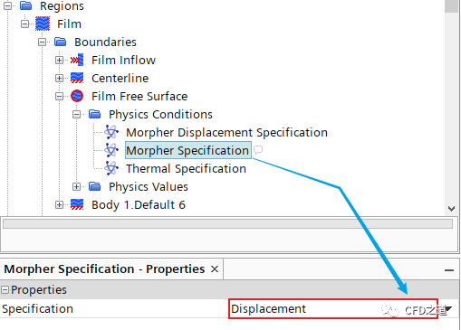
修改边界Body 1.Default 5名称为Film Free Surface,并修改其类型为Free Steam -
选中模型树节点Film Free Surface > Physics Conditions > Morpher Specification,设置 Specification为Displacement
-
修改边界Body 1.Default 6名称为Chill Roll,并修改其类型为Free Steam -
鼠标双击模型树节点Chill Roll,弹出参数设置对话框,如下图所示设置参数
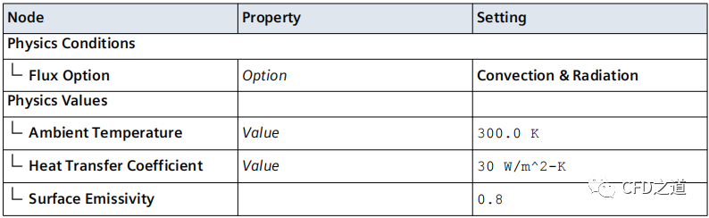
8 指定液膜换热
-
鼠标双击模型树节点Regions > Film,设置以下参数
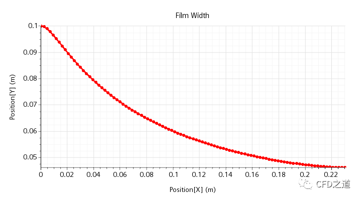
9 绘制液膜宽度与厚度曲线
1、绘制液膜宽度
-
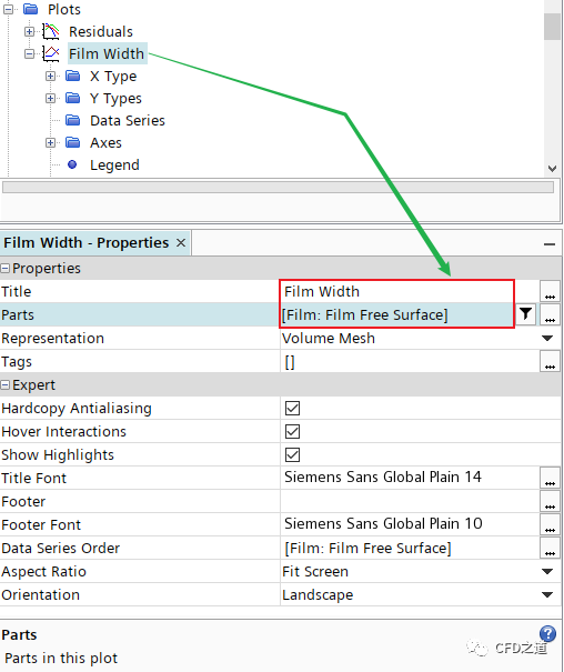
右键选择模型树节点Plot,点击弹出菜单项New Plot > XY Plot,修改新创建的节点名为Film Width -
选中节点Film Width,指定 Parts为Film Free Surface
-
设置X轴 -
选择节点Film Width > X Type,指定 Data Type为Scalar -
选择节点X Type > Scalar Function,指定 Field Function为Position > Laboratory > X -
设置Y轴 -
选择节点Film Width > Y Types > Y Type 1,激活选项Smooth Value -
选择节点Y Type 1 > Scalar Function,指定 Field Function为Position > Laboratory > Y
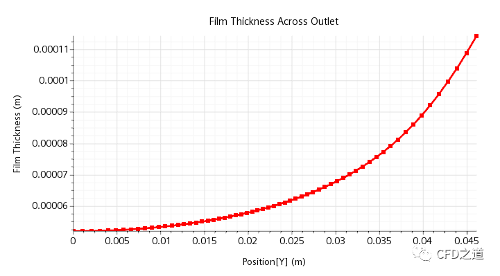
2、绘制液膜厚度
-
右键选择模型树节点Plot,点击弹出菜单项New Plot > XY Plot,修改新创建的节点名为Film Thickness
-
选中节点Film Thickness,指定
Parts为Chill Roll -
设置X轴
-
选择节点Film Thickness > X Type,指定 Data Type为Scalar -
选择节点X Type > Scalar Function,指定 Field Function为Position > Laboratory > Y -
设置Y轴
-
选择节点Film Thickness > Y Types > Y Type 1,激活选项Smooth Value -
选择节点Y Type 1 > Scalar Function,指定 Field Function为Film Thickness
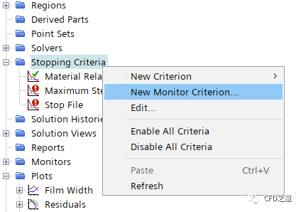
10 设置停止标准
-
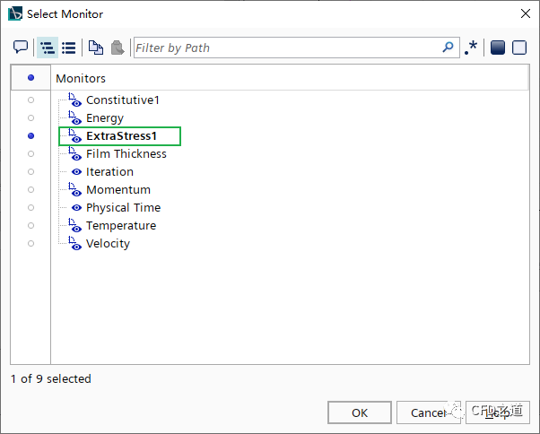
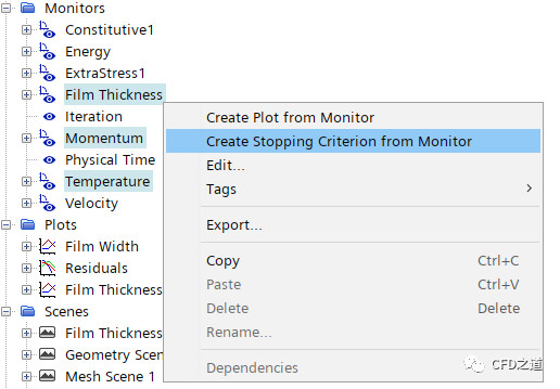
右键选择模型树节点Stopping Criteria,点击菜单项New Monitor Criterion…
-
弹出对话框中选择ExtraStress1,点击OK按钮关闭对话框
-
如下图所示将Film Thickness、Momentum、Temperature添加到Monitor中
-
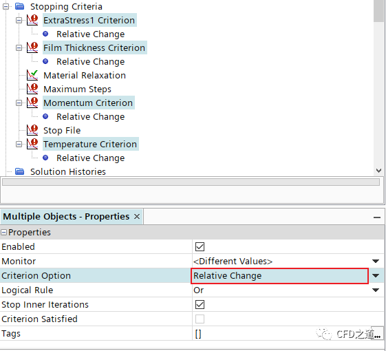
如下图所示设置终止标准为Relative Change
-
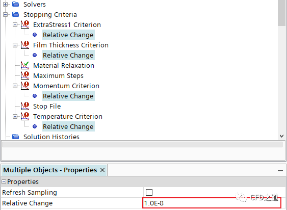
如下图所示设置Relative Change为1e-8
-
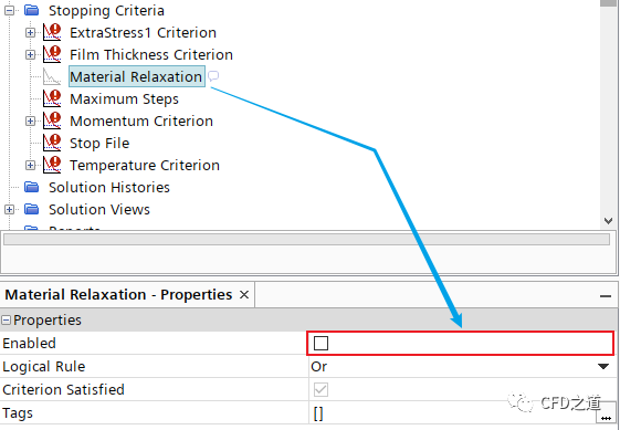
选中节点Material Relaxation,属性窗口中取消激活选项Enable,如下图所示
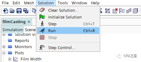
11 进行计算
-
点击菜单Solution → Run开始计算
12 计算结果
-
液膜宽度变化
-
液膜厚度变化
-
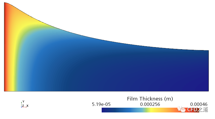
厚度分布
-
温度分布
-
速度矢量图
注:本算例取自STAR CCM+随机算例。
”
本篇文章来源于微信公众号: CFD之道


评论前必须登录!
注册