
本算例演示利用STAR CCM+中的网格重构功能模拟仿真摆线泵内部流场。
1 问题描述
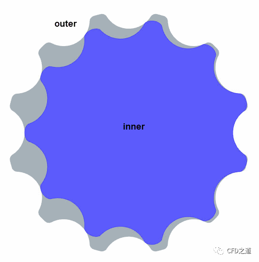
摆线泵是一种包含有内转子和外转子的装置,其内转子和外转子具有与其齿数相关的不同转速,当转子旋转时,通过转子间动态变化的容积将流体从入口输送到出口。
摆线泵模拟的最大问题是处理转子之间的狭小间隙。转子旋转会导致小间隙中的网格质量降低。在STAR CCM+中可以使用Remeshing模型处理此类问题。
案例所模拟的摆线泵外转子包含12个齿,内转子包含11个齿,其的转速与齿数满足以下函数关系:
几何模型如下图所示。
2 STAR CCM+设置
-
启动STAR CCM+
2.1 导入文件
-
利用菜单 File > Load导入仿真文件gerotor_start.sim
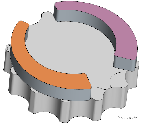
几何模型如下图所示。
放大图形可以看到齿间存在小的间隙。
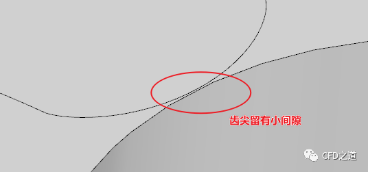
注:计算过程中,两齿不能完全接触。
”
2.2 设置网格参数
导入的仿真文件中已经预置了进出口部分的网格参数,这里只需要指定两个转子的网格参数即可。
当网格重构时,网格生成管道需确保泵处于正确的位置。此外,齿间间隙较小,可以应用Directed Mesh方法以减少轴向方向上的网格数量。为摆线体定义两个运动变换操作,一个布尔减操作及一个Directed Mesh操作。
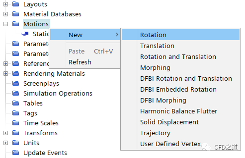
1、定义两个旋转运动
-
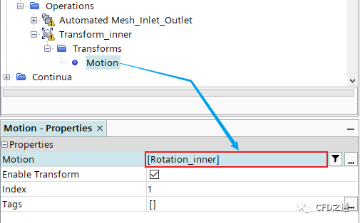
右键选择模型树节点Tools > Motions,点击弹出菜单项New → Rotation,修改新增的节点名称为Rotation_inner
-
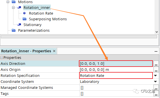
选中节点Rotation_inner,如下图所示设置 -
指定 Axis Direction为**[0,0,1]** -
指定 Axis Origin为**[0,0,0]** -
指定 Rotation Specification为Rotation Rate
-
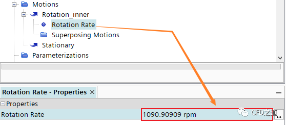
选中节点Motions > Rotation_inner > Rotation Rate,指定 Rotation Rate为1090.90909 rpm
-
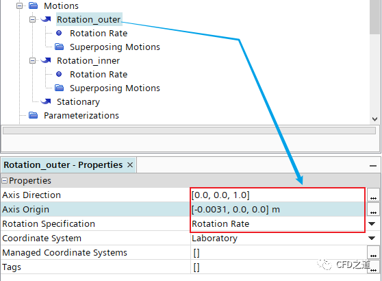
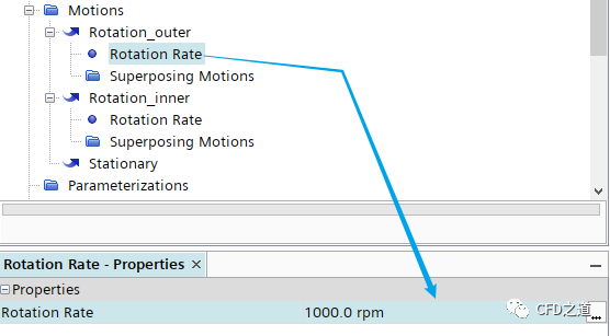
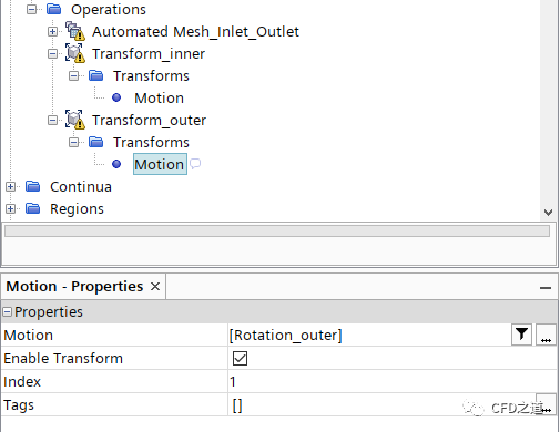
相同方式创建另一个运动,将其命名为Rotation_outer,并指定如下图所示参数
2、定义区域旋转
-
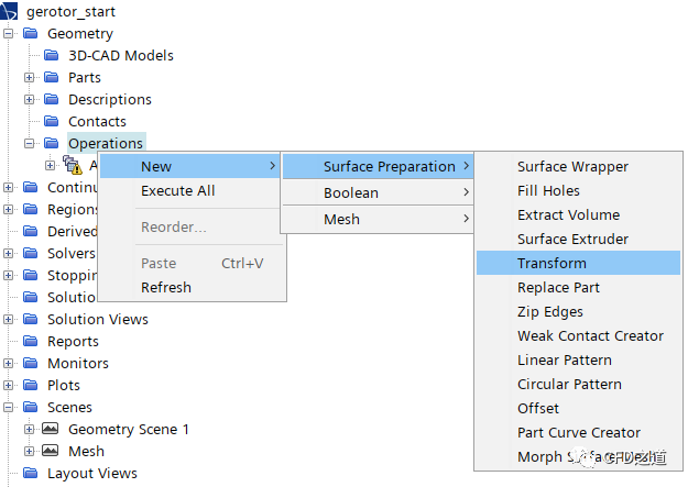
右键选择模型树节点 Geometry > Operations ,点击弹出菜单项 New > Surface Preparation > Transform创建变换
-
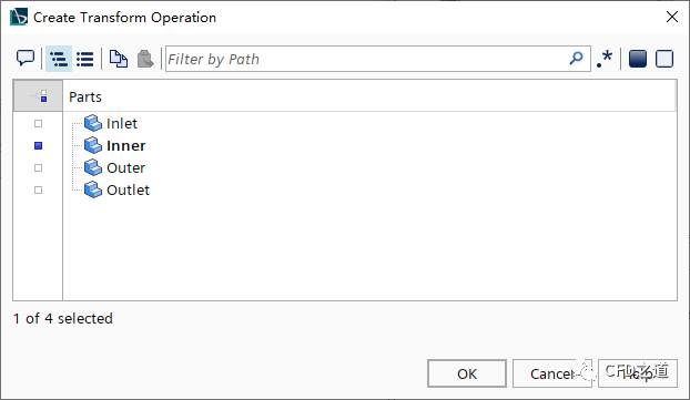
在弹出的对话框中选择Inner并点击OK按钮确认选择
-
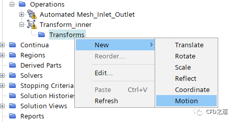
修改节点Transform名称为Transform_inner,右键选择节点Transform_inner > Transforms,点击弹出菜单项New > Motion创建新节点
-
选中节点Motion,指定参数 Motion为Rotation_inner
-
相同的方式创建另一个运动,命名为Transform_outer,指定其Part为Outer,其运动为Rotation_outer
3、构造计算区域
-
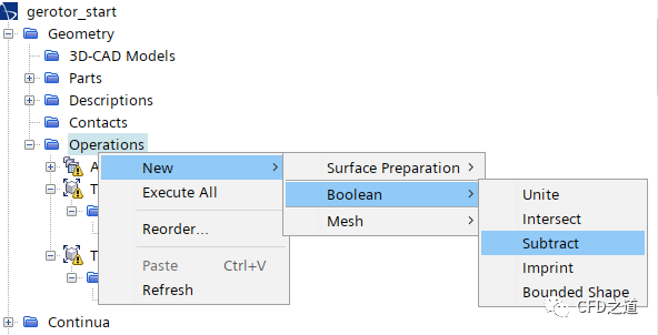
右键选择节点Operations,点击弹出菜单项New → Boolean → Substract打开操作对话框
-
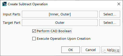
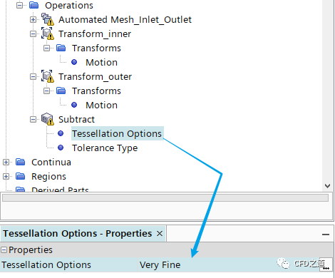
如下图所示,选择 Input Parts为Inner与Outer,指定Target Part为Outer,激活选项Perform CAD Boolean,点击OK按钮确认选择
-
如下图所示,选中节点Tessellation Options,指定参数为Very Fine
-
选中模型树节点Parts > Subtract ,将节点名称修改为PumpFluid
4、设置网格参数
-
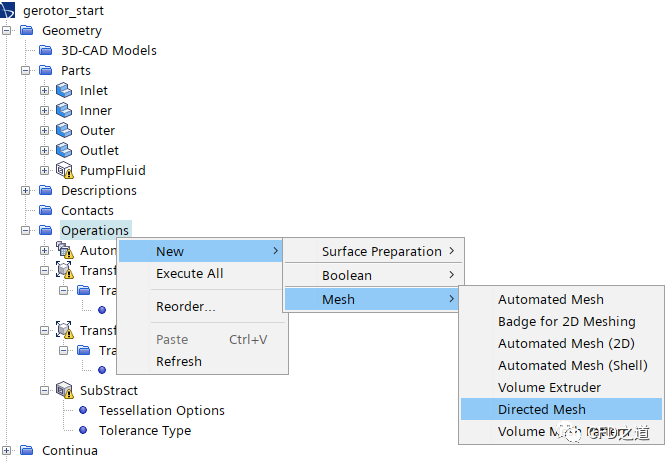
右键选中模型树节点Operations,点击弹出菜单项New → Mesh → Directed Mesh添加扫略网格
-
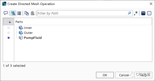
弹出的对话框中选择部件PumpFluid,如下图所示
-
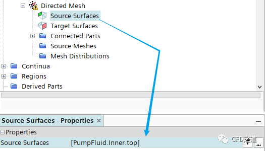
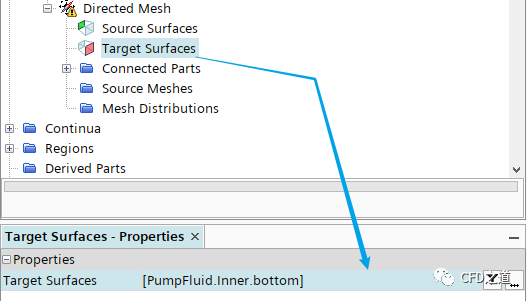
指定 Source Surfaces为PumpFluid.Inner.top
-
指定 Target Surfaces为PumpFluid.Inner.bottom
-
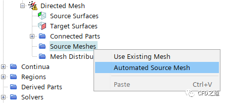
右键选择节点Source Meshes,点击弹出菜单项Automated Source Mesh
-
弹出对话框中选择PumpFluid,指定网格生成方法为Quadrilaterial Mesher与Prism Layer Mesher

-
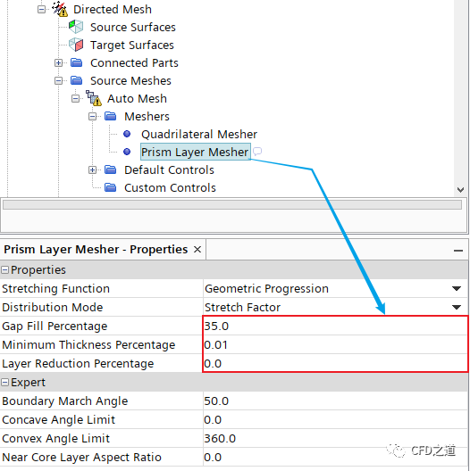
选中节点Source Meshes > Auto Mesh > Meshers > Prism Layer Mesher,如下图所示指定参数
-
进入节点Default Controls,按下表所示指定参数
| 节点 | 属性 | 参数值 |
|---|---|---|
| Base Size | Base Size | 0.001 m |
| Minimum Surface Size | Percentage of Base | 0.5 |
| Prism Layer Total Thickness | Percentage of Base | 10 |
-
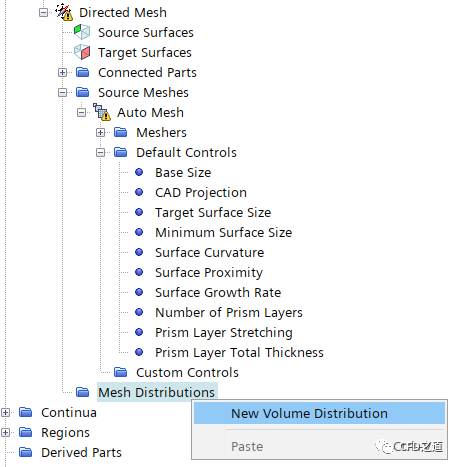
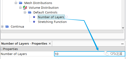
右键选中模型树节点Mesh Distributions,点击弹出菜单项New Volume Distribution创建体网格分布
-
如下图所示选择部件PumpFluid,点击OK按钮确认选择
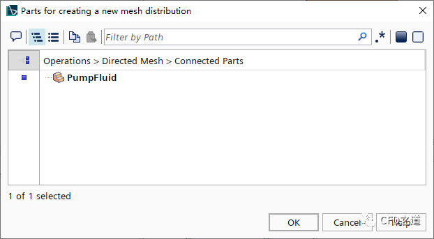
-
指定 Number of Layers为10,生成10层边界层网格
2.3 创建部件接触
-
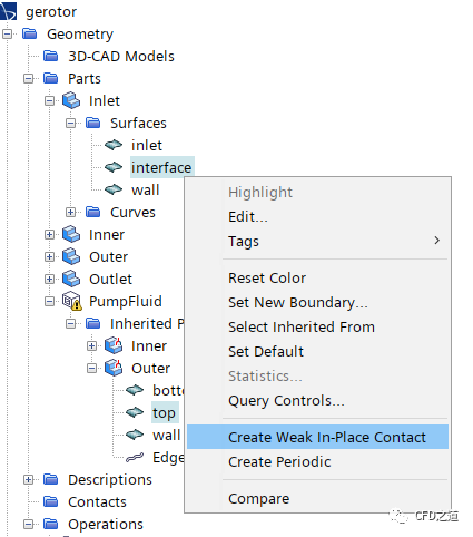
如下图所示,按键盘 CTRL键同时选中节点Inlet > Surface > interface与PumpFluid > Outer > top,点击鼠标右键并选择弹出菜单项Create Weak In-Place Contact创建弱接触
-
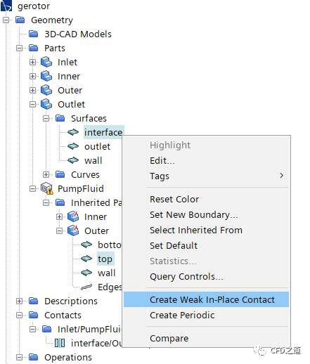
相同方式选中节点Outlet > Surface > interface与PumpFluid > Outer > top创建另一对弱接触
-
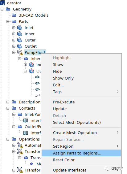
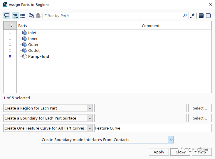
右键选择节点PumpFluid,点击弹出菜单项Assign Part to Regions… 分配计算区域
-
如下图所示设置参数
-
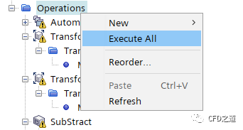
右键选择节点Operations,点击弹出菜单项Execute All执行所有操作
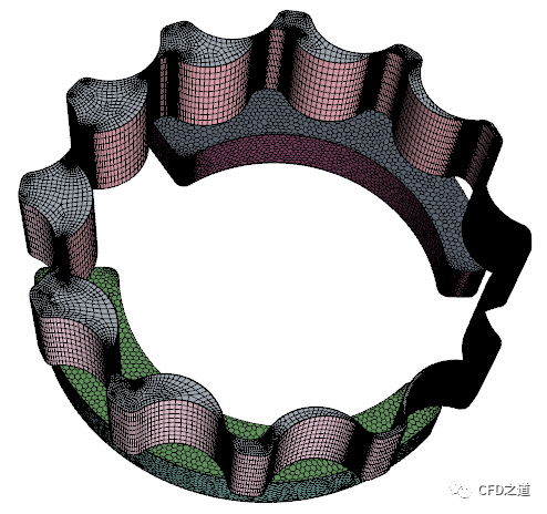
生成的网格如下图所示。
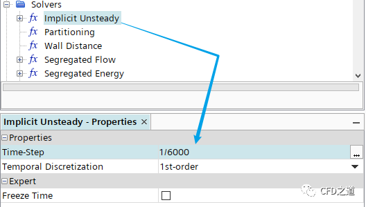
2.4 设置时间步长
模拟运动时,时间步长应与网格运动相匹配。运动对象周围的流场随对象的运动而变化。因此时间步长应足够小,以捕获运动引起的变化。本案例要求解旋转过程中小间隙内的流动,因此选择时间步长大小以匹配一个旋转角度。当涉及复杂物理时,例如多相流,时间步长还应该进一步减小。
在本教程中,两个转子的配置如下所示:
| 转子 | 齿数 | 几何角度 | 旋转速度 | 时间周期 | 时间步数 | 时间步长 |
|---|---|---|---|---|---|---|
| Outer Rotor | 12 | 30° | 1000 RPM | 0.005 | 30 | 1/6000 s |
| Inner Rotor | 11 | 32.73° | 100.90909RPM | 0.005 | 30 | 1/6000 s |
-
选中模型树节点Solvers > Implicit Unsteady,设置 Time-Step为1/6000
2.5 设置网格重构
-
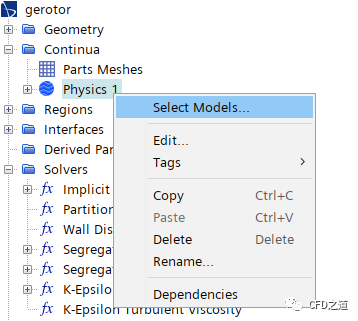
右键选择模型树节点Physics 1,点击弹出菜单项Select Models… 打开模型选择对话框
-
如下图所示选择选项Remeshing
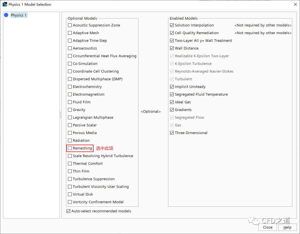
注:其它的选项按常规流动计算设置,这里已经预先选择完毕。
”
-
选中节点Remeshing,如下图所示设置 -
指定 Mesh Operations为Directed Mesh -
选中激活选项 Repeating Meshes
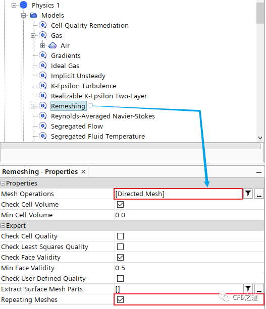
-
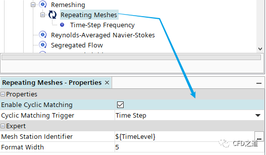
选择节点Remeshing > Repeating Meshes,激活选项 Enable Cyclic Matching
-
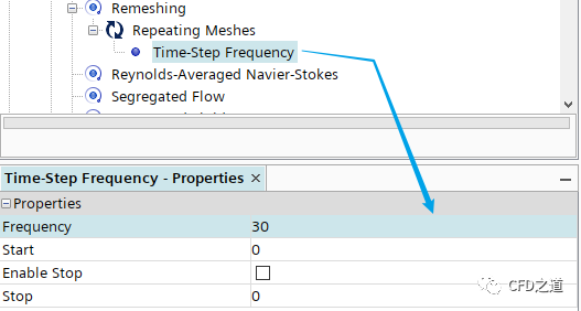
选中选项Remeshing > Repeating Meshes > Time-Step Frequency,指定 Frequency为30
-
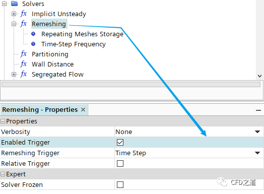
选中节点Solvers > Remeshing,激活选项 Enable Trigger
-
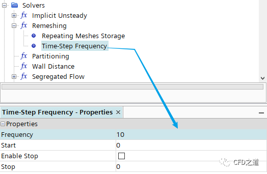
选中节点Solvers > Remeshing > Time-Step Frequency的频率为10
2.6 设置变形运动及边界条件
摆线转子壁面的运动通过变形器来实现。
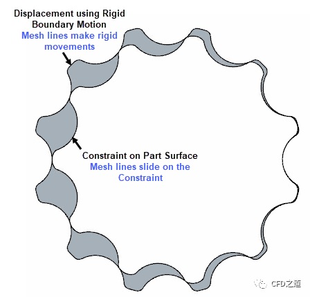
为了避免小间隙中的网格发生极度变形,需要为PumpFluid区域的内壁面指定为Constraint变形器边界,使其沿内部几何部件的壁面滑动。通过让顶点自由滑动,与强制刚性位移相比,变形网格的强度更小。对于具有小间隙的变形问题,此方法可在不出现负单元格的情况下,在多个时间步上进行变形。
通常,变形过程必须在没有负网格的情况下至少在2-3个时间步内成功,否则网格重构求解器将激活恒定重构,而不会改善网格质量。建议对没有锐边的曲面使用约束方法。否则在旋转期间将无法正确表示曲面。
-
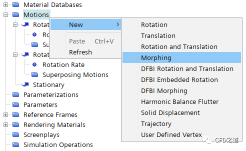
右键选择节点Tools > Motions ,选择弹出菜单项New > Morphing创建Morphing
-
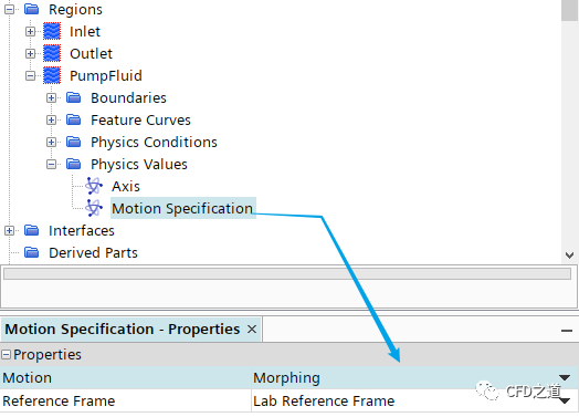
选中节点Regions > PumpFluid > Physics Value > Motion Specification,指定 Motion为Morphing
-
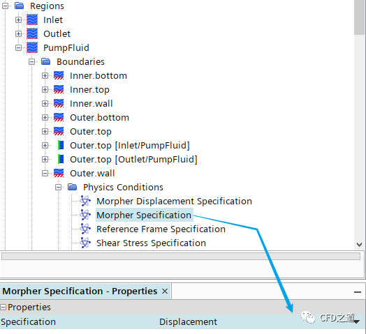
选择节点Regions > PumpFluid > Boundaries > Outer.wall > Physics Conditions > Morpher Specification,指定 Specification为Displacement
-
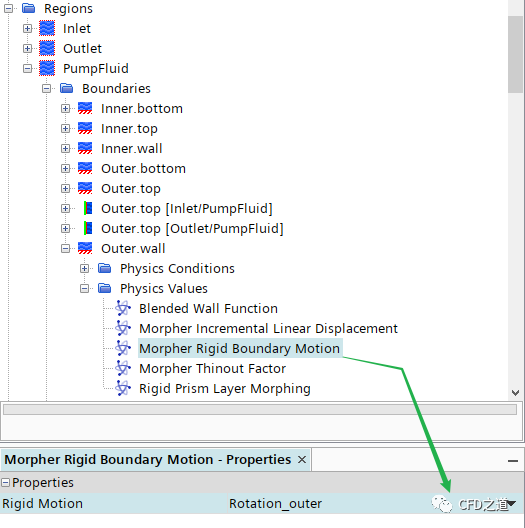
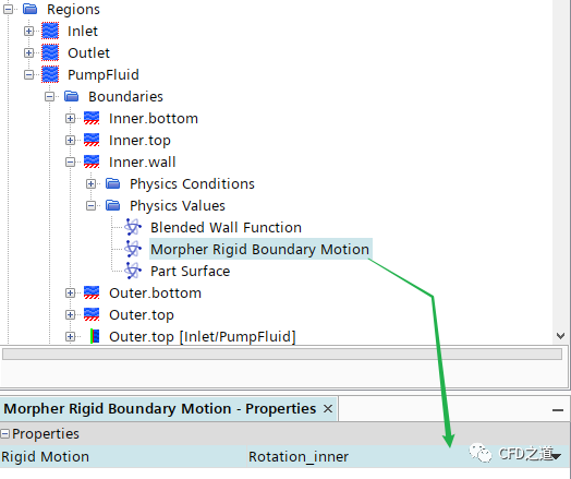
选择节点Regions > PumpFluid > Boundaries > Outer.wall > Physics Values > Morpher Rigid Boundary Motion,指定 Rigid Motion为Rotation_outer
-
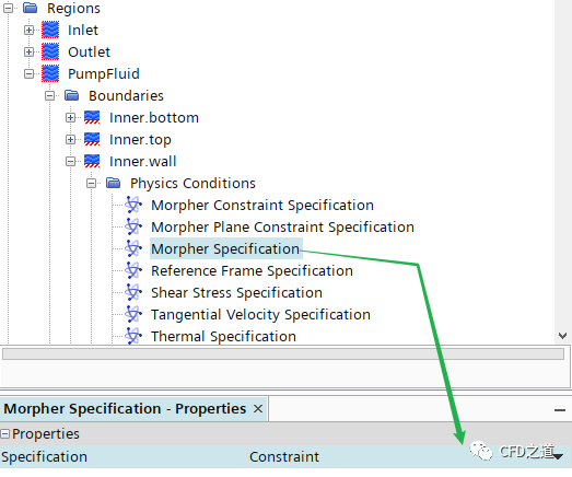
选中节点Regions > PumpFluid > Boundaries > Inner.wall > Physics Conditions > Morpher Specification,指定 Specification为Constraint
-
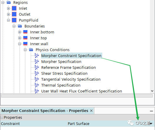
选中节点Physics Conditions > Morpher Constraint Specification,指定 Constraint为Part Surface
-
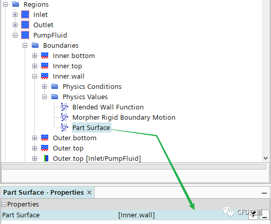
选择节点Physics Values > Part Surface,指定 Part Surface为Inner.wall
-
选择节点Physics Values > Morpher Rigid Boundary Motion,指定 Rigid Motion为Rotation_inner
-
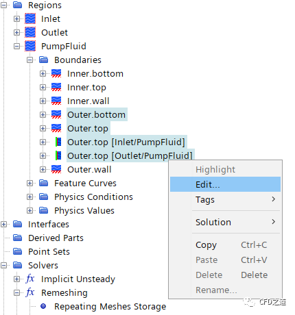
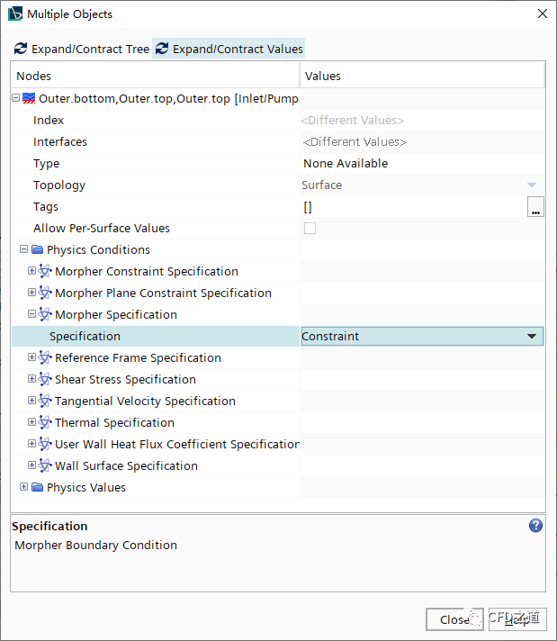
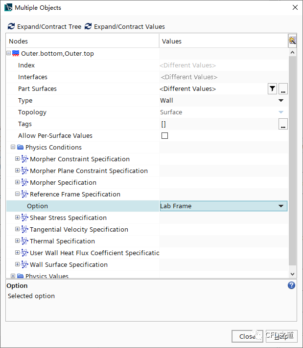
同时选中节点Outer.bottom, Outer.top, Outer.top[Inlet/PumpFluid], Outer.top[Outlet/PumpFluid],点击右键菜单项Edit… 打开设置面板
-
指定Physics Conditions > Morpher Specification为Constraint
-
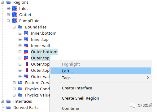
同时选中节点Outer.bottom及Outer.top,点击右键菜单项Edit… 打开设置面板
-
指定参数Physics Conditions > Reference Frame Specification为 Lab Frame
2.7 进行计算
-
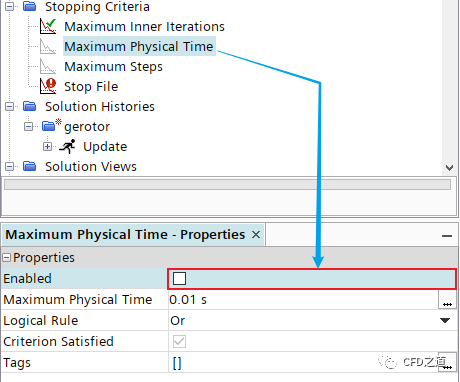
选中节点Stopping Criteria > Maximum Physical Time,取消激活选项Enabled
-
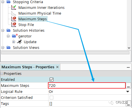
选中节点Maximum Steps,设置 Maximum Steps为720
-
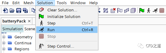
点击菜单Solution → Run进行计算
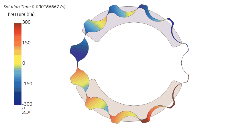
3 计算结果
-
网格运动

-
压力随时间变化
本案例来自STAR CCM+随机自带案例,为最近几个版本新增案例。
类似这种狭缝结构在泵类模型中经常会碰到,目前可选的方法包括利用重叠网格、网格重构等。但这些方法都有各自的麻烦之处。
STAR CCM+的Remeshing功能计算效率较低,计算一段时间时间后要停下来重新生成网格,如果重生成的网格与之前的网格差距过大,会造成极大的插值误差,因此在使用此方法的过程中,尽量减小时间步长,以避免网格重构前后的网格节点差距过大。
本篇文章来源于微信公众号: CFD之道


评论前必须登录!
注册