
本算例演示利用Fluent研究罐式燃烧器内甲烷与空气的混合燃烧过程。
算例包含的内容:
-
在Fluent Meshing中对燃烧室进行网格划分 -
使用涡耗散模型模拟燃烧过程 -
使用稳态小火焰模型模拟燃烧过程
1 问题描述
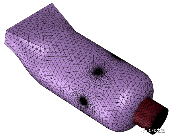
计算所采用的几何模型及边界示意如下图所示。
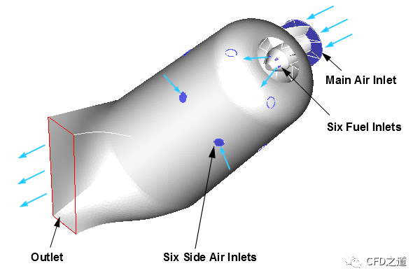
压缩的一次空气通过燃烧器底部的主进气口以10 m/s的速度进入燃烧室。六个涡流叶片引导进入燃烧器内的空气,并促进其与甲烷的混合以实现适当的燃烧。甲烷通过六个燃料入口以40米/秒的速度喷射进入燃烧器。当反应混合物通过燃烧器时,二次空气通过主燃烧区下游的六个二次空气入口以6 m/s的速度进入燃烧室。这有助于提高燃烧效率,并在燃烧室内壁暴露于热反应流时冷却罐壁。燃料和氧化剂以300 K的温度进入燃烧室。
2 网格生成
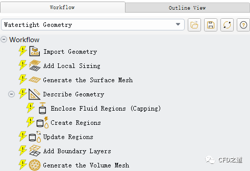
利用Fluent Meshing中的Watertight Geometry工作流创建计算网格。
-
启动Fluent Meshing,启用Watertight Geometry工作流程
2.1 导入几何
-
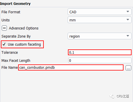
进入模型树节点 Import Geometry -
点击按钮Advanced Options ,设置 Separate Zone By为region -
设置 Tolerance为0.1 -
指定 File Name为can_combustor.pmdb
2.2 增加局部尺寸控制
-
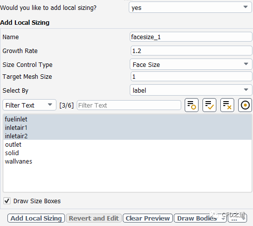
进入模型树节点 Add local sizing,选择Would you like to add local sizing为yes -
设置Size Control Type为Face Size -
指定Target Mesh Size为1 -
选择边界列表项fuelinlet, inletair1及inletair2 -
点击按钮Add Local Sizing添加尺寸控制
-
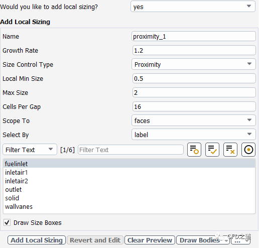
对燃料入口边界添加尺寸控制 -
设置 Size Control Type 为 Proximity -
指定 Local Min Size为0.5, 指定Max Size 为2 -
设置Cells Per Gap 为16 -
选择列表项对象为fuelinlet -
点击按钮Add Local Sizing
-
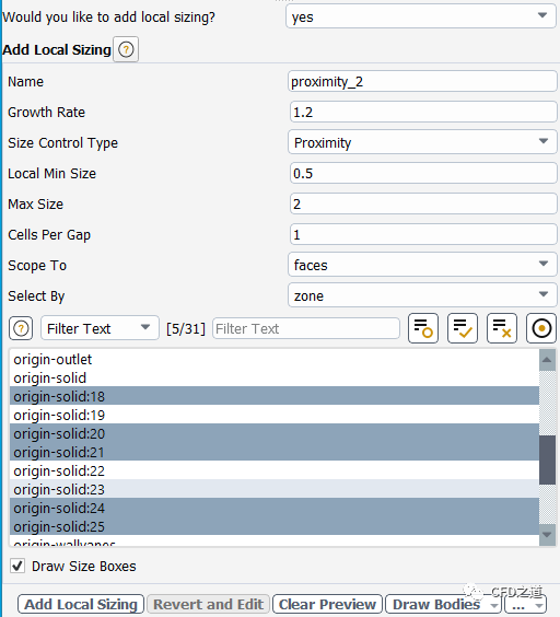
对入口叶片进行尺寸控制 -
设置 Size Control Type 为 Proximity -
指定 Local Min Size为0.5, 指定Max Size 为2 -
设置Select By 为zone -
选择列表项origin-solid:18, origin-solid:20, origin-solid:21, origin-solid:24 及 origin-solid:25 -
点击按钮Add Local Sizing
-
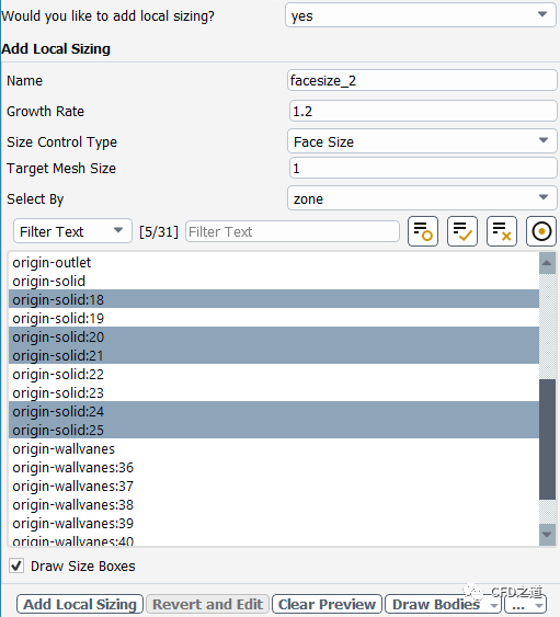
对入口叶片进行面尺寸控制 -
设置 Size Control Type 为 Face Size -
指定 Target Mesh Size为1 -
设置Select By 为zone -
选择列表项origin-solid:18, origin-solid:20, origin-solid:21, origin-solid:24 及 origin-solid:25 -
点击按钮Add Local Sizing
2.2 生成面网格
-
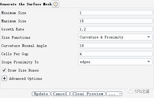
进入模型树节点 Generate the surface mesh -
设置Minimum Size 为1 -
设置 Maximum Size 为15 -
设置Cells Per Gap 为4 -
点击按钮 Generate the Surface Mesh 生成面网格
面网格如下图所示。
2.3 描述几何
-
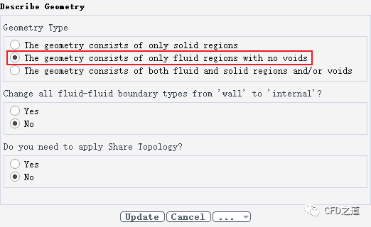
进入模型树节点 Describe the geometry,如下图所示设置 -
点击按钮Describe Geometry
2.4 更新边界
-
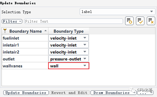
进入模型树节点 Update the boundaries,修改边界wallvanes的边界类型为wall -
点击按钮 Update Boundaries
2.5 更新区域
-
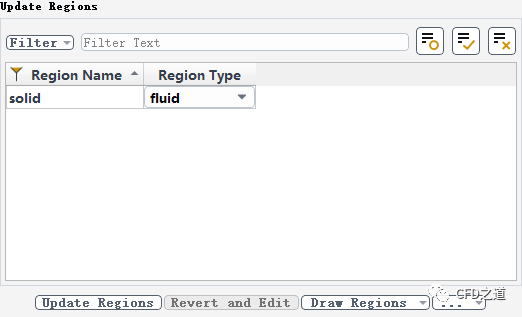
进入节点 Update the regions,保持默认设置 -
点击按钮Update Regions
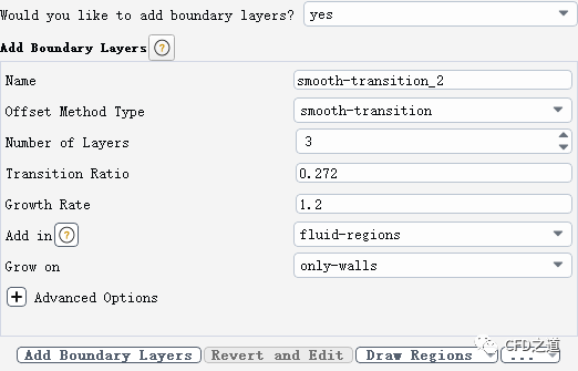
2.6 添加边界层参数
-
进入模型树节点 Add boundary layers,采用默认设置 -
点击按钮Add boundary layers
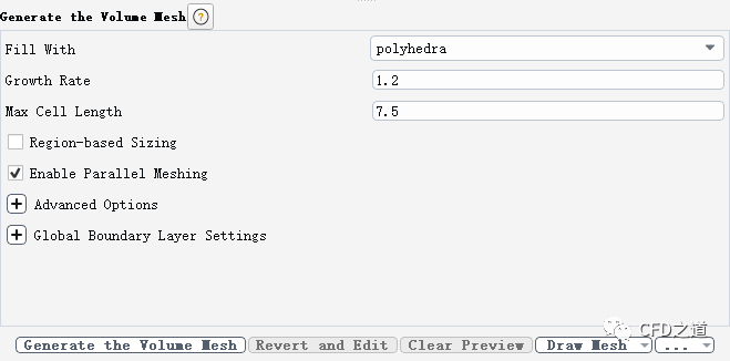
2.8 生成体网格
-
进入模型树节点 Generate the volume mesh -
指定Max Cell Length 为7.5 -
点击按钮Generate the Volume Mesh 生成计算网格
生成的体网格如下图所示。
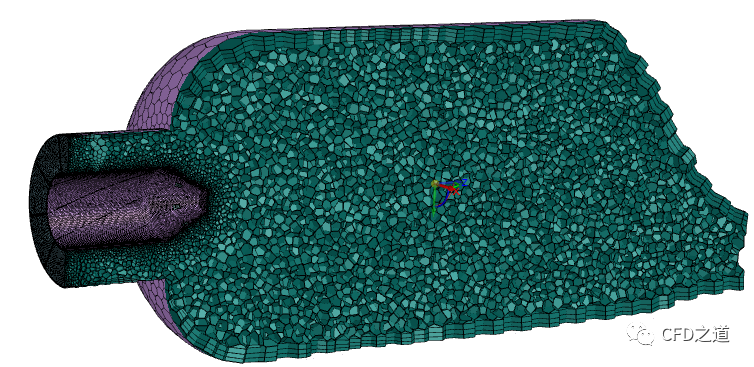
-
点击按钮Switch to Solution 切换至求解模式
3 ED模型计算燃烧
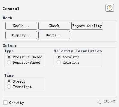
3.1 General设置
-
保持默认设置
3.2 Models设置
-
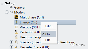
激活能量方程
-
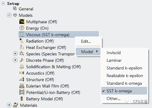
采用SST k-omega湍流模型
-
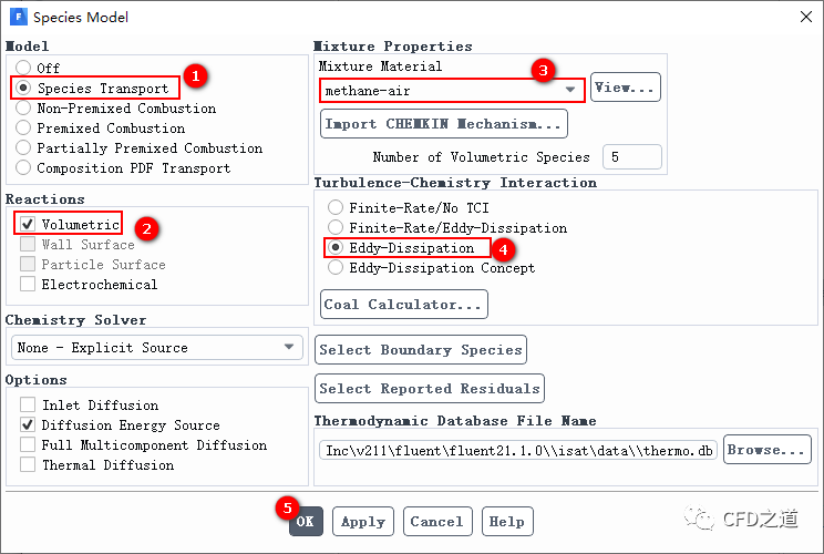
设置组分输运模型
3.3 边界条件设置
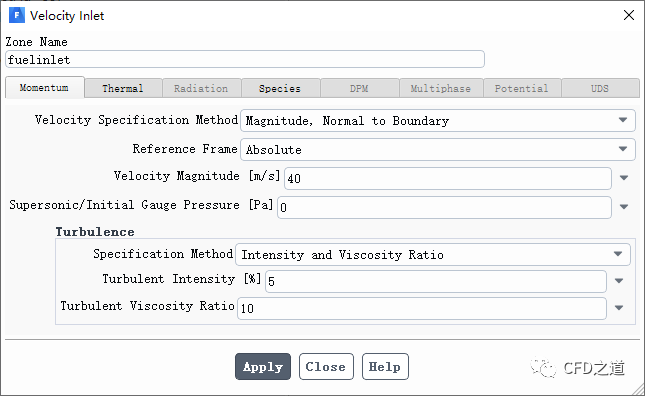
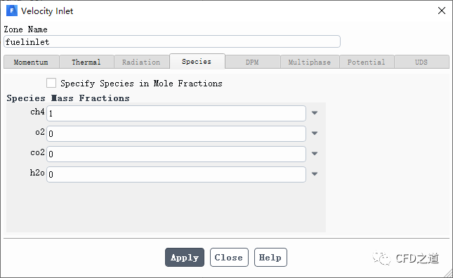
1、fuelinlet边界
-
指定 fuelinlet边界入口速度40 m/s
-
进入 Species标签页,指定组分ch4的质量分数为1 ,表示从该边界介入计算域的组分全部为甲烷
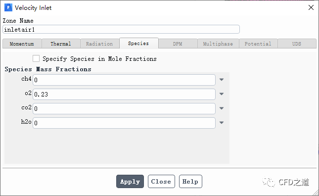
2、inletair1边界
-
指定边界 inletair1的入口速度为10 m/s

-
指定该边界入口组分 o2质量分数为0.23 ,表示进入的是空气
3、inletair2边界
-
指定边界 inletair1的入口速度为6 m/s
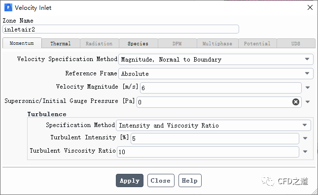
-
指定该边界入口组分 o2质量分数为0.23 ,表示进入的是空气

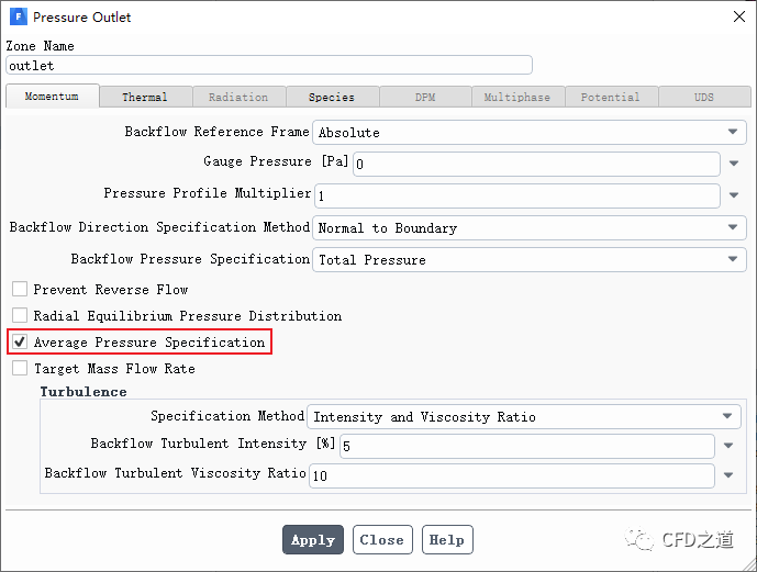
4、outlet设置
-
激活选项 Average Pressure Specification
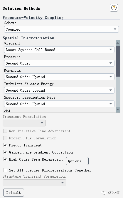
3.4 Methods设置
-
激活选项High Order Term Relaxation ,其他参数保持默认设置
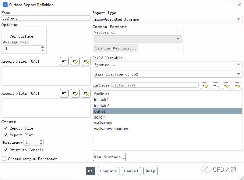
3.5 监测物理量
-
监测出口位置的CO3质量分数
3.6 初始化设置
-
采用 Hybrid Initialization进行初始化

3.7 计算参数设置
-
指定 Time Scale Factor为5 -
指定 Number of Iterations为500

注:参数Time Scale Factor可以用于调节伪瞬态计算的时间步长,该参数值越大收敛越快,但相应的计算稳定性也越差。
”
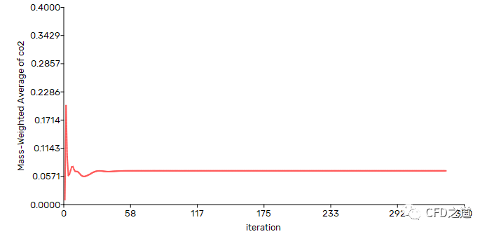
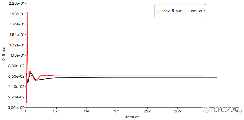
监测得到的出口CO2质量分数变化曲线如下图所示。
-
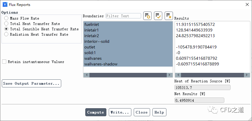
查看进出口质量流量
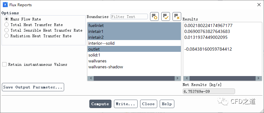
-
查看系统内能量平衡
3.8 计算结果
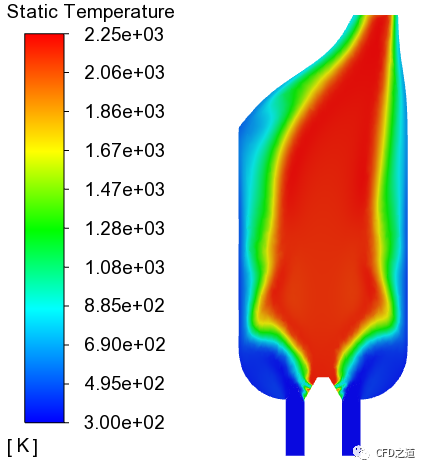
-
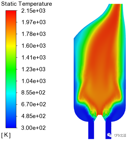
y=0面上温度分布
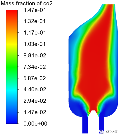
-
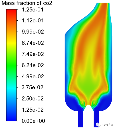
y=0面上co2质量分数分布
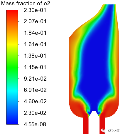
-
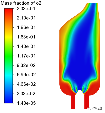
y=0面上o2质量分数分布
4 稳态扩散小火焰模拟
前面使用涡耗散模型模拟燃烧过程。下面将使用稳态扩散小火焰模型来模拟湍流非预混燃烧过程。稳态扩散小火焰模型可以模拟由于湍流应变引起的局部化学非平衡。
在稳态扩散小火焰模型中,化学反应发生在一个局部一维的薄层区域,称为“小火焰”,湍流火焰由这些小火焰的集合来表示。利用详细的化学反应动力学来描述燃烧过程,假设化学反应对湍流应变反应迅速,当应变弛豫到零时,化学反应趋于平衡。尽管有趋向于平衡的趋势,小火焰模型计算结果通常比涡流耗散模型或一步或两步有限速率模型能产生更精确的结果。这是因为所有的化学细节都包括在内,使得捕捉一些更快的中间反应成为可能。为了模拟湍流混合,在运行时使用概率密度函数(PDF)表作为查找表。
4.1 Models设置
-
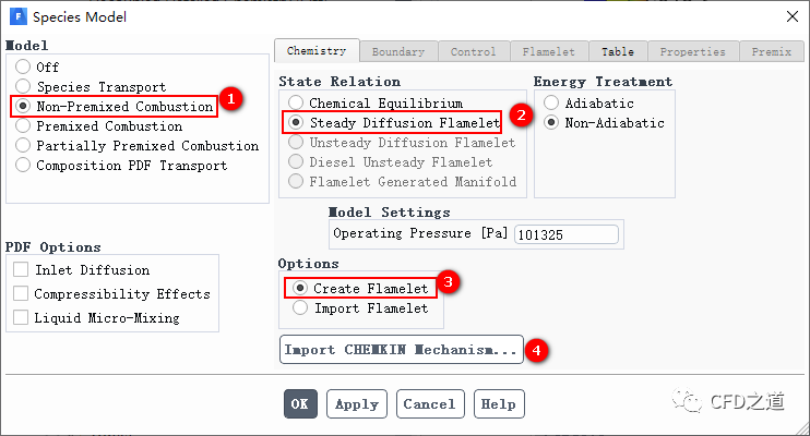
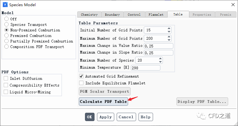
修改 Species Model对话框中的参数 -
选择模型Non-Premixed Combustion -
激活选项Steady Diffusion Flamelet -
选择选项 Create Flamelet -
点击按钮**Import CHEMKIN Mechanism…**打开机理导入对话框
-
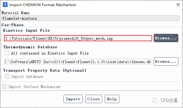
如下图所示导入甲烷燃烧机理文件grimech30_50spec_mech.inp
-
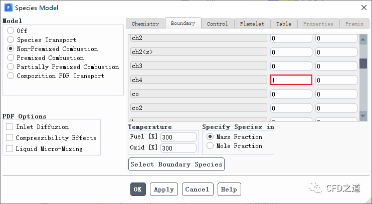
进入 Boundary标签页,指定Fuel组分ch4的质量分数为1 ,其他参数保持默认
-
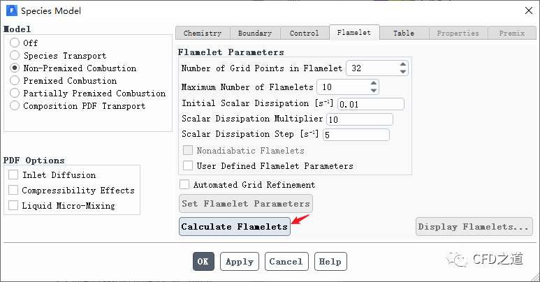
进入 Flamelet标签页,采用默认参数设置,点击按钮Calculate Flamelets 创建小火焰
-
进入 Table标签页,采用默认参数设置,点击按钮Calculate PDF Table 创建PDF表
-
利用菜单File → Write → PDF... 保存PDF表
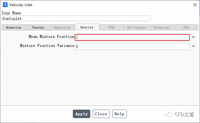
4.2 边界条件设置
-
修改边界 fuelinlet的参数,指定Mean Mixture Fraction为1
-
其他边界保持默认设置
注:这里设置Mean Mixture Fraction为1,表示从该边界进入到计算域中的介质全部为燃料。
”
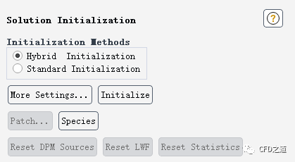
4.3 初始化计算
-
采用 Hybrid Initialization进行初始化
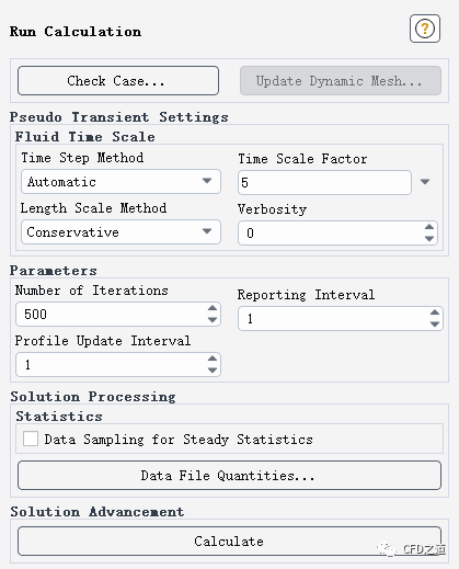
4.4 迭代计算
-
指定 Time Scale Factor为5 -
指定 Number of Iterations为500
4.5 计算结果
-
y=0面上温度分布,可以看到计算得到的最高温度要比ED模型低
-
y=0面上co2质量分数分布
-
y=0面上o2质量分数分布
-
两种计算方法监测得到的出口位置CO2浓度比较
相关文件:
链接:https://pan.baidu.com/s/1r4usHetiGIo4YSQik2DBmw 提取码:3au3
”
本篇文章来源于微信公众号: CFD之道


评论前必须登录!
注册