
本教程演示利用Fluent计算再入舱返回时其外部的高超声速流动。
1 案例介绍
本案例中模拟的再入舱速度及环境条件为其在大约50 km高度地球大气层的条件。
本文演示以下操作:
-
使用watertight工作流创建计算网格 -
用高速数值模拟方法,用 two-temperature模型模拟能量,用appropriate模型模拟空气特性 -
使用SST k-omega湍流模型 -
使用密度基耦合求解器
2 模型描述
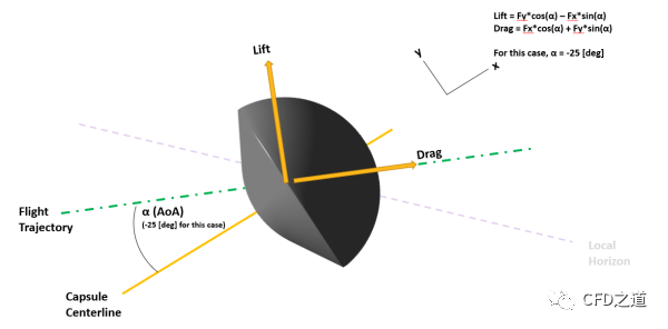
该问题考虑攻角α=-25°及自由流马赫数17.0时再入舱周围的流动。再入舱的几何形状如图所示,图中还表示了给定情况下的升力和阻力方向。在本教程中,假设再入舱周围的流动是对称的。
3 计算网格
在Fluent Meshing中生成计算网格。
-
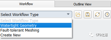
启动Fluent Meshing,选择使用Watertight Geometry工作流程,如下图所示
-
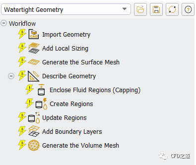
模型树节点如下图所示
-
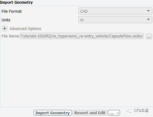
导入CAD几何模型 -
选择 Import Geometry节点 -
选择 Units为m -
指定几何文件CapsuleFlow.scdoc -
点击按钮Import Geometry导入几何模型
注意:再入舱的几何被包围在一个合适的流体域内,该流体域为一系列攻角提供不同的流入和流出区域,并避免在这种流中形成的弓形激波与流入面接触..
”
-
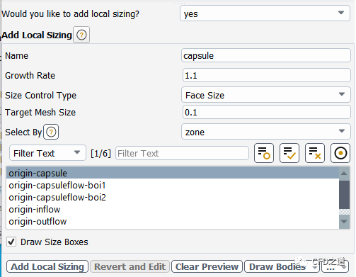
设置 Local Sizing指定局部网格尺寸 -
激活 Add Local Sizing -
指定 Name为capsule -
指定Growth Rate为1.1 -
指定 Target Mesh Size为0.1 -
选择区域为origin-capsule -
点击按钮Add Local Sizing
-
添加BOI网格控制 -
指定 Name为boi_1 -
指定Growth Rate为1.1 -
指定 Size Control Type为Body Of Influence -
指定 Target Mesh Size为0.2 -
选择区域为capsuleflow-boi1 -
点击按钮Add Local Sizing

-
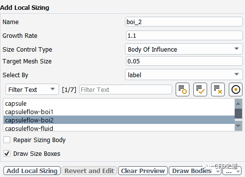
添加BOI网格控制 -
指定 Name为boi_2 -
指定Growth Rate为1.1 -
指定 Size Control Type为Body Of Influence -
指定 Target Mesh Size为0.05 -
选择区域为capsuleflow-boi2 -
点击按钮Add Local Sizing
-
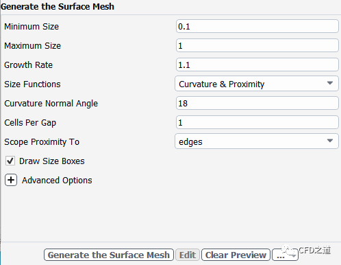
生成面网格 -
进入面板Generate the Surface Mesh -
指定 Minimum Size为0.1 -
指定 Maximum Size为1 -
指定 Growth Rate为1.1 -
点击按钮Generate the Surface Mesh生成面网格
-
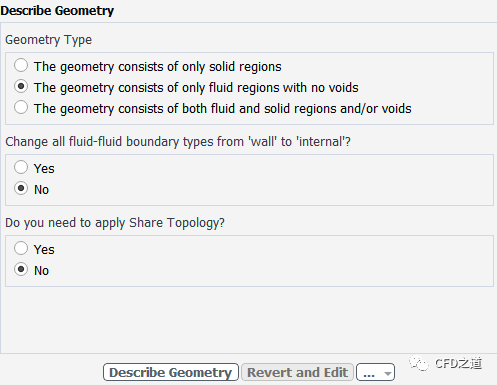
描述几何模型 -
选择选项 The geometry consists of only fluid regions with no voids -
其他参数保持默认设置
-
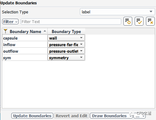
进入面板 Update Boundaries,如下图所示
-
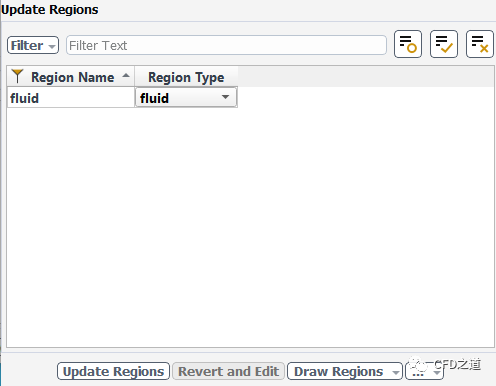
进入面板 Update Regions,如下图所示设置
-
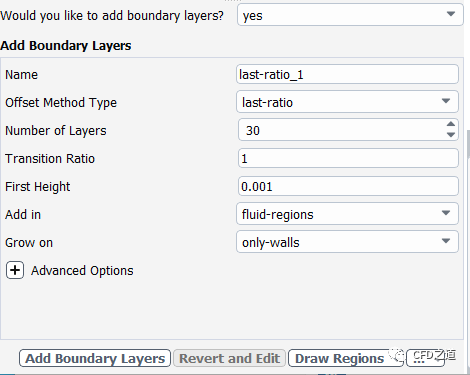
添加边界层参数 -
指定参数 Offset Method Type为last-ratio -
指定参数 Number of Layers为30 -
指定参数 Transition Ratio为1 -
指定参数 First Height为0.001 -
点击按钮Add Boundary Layers
-
进入面板Generate the Volume Mesh生成计算网格 -
选择参数 Fill With为 polyhedra -
指定参数 Max Cell Length为1 -
点击按钮 Generate the Volume Mesh生成计算网格

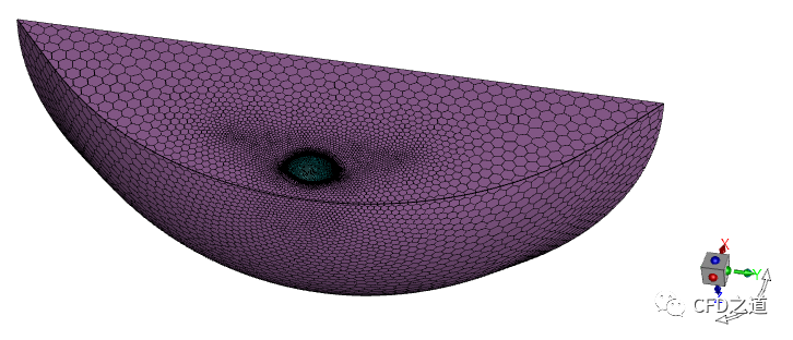
生成计算网格如下图所示。
-
**File→ Write → Mesh…**保存网格文件 -
Switch to Solution进入求解模式
4 Fluent设置
4.1 General设置
-
采用Density-Based求解器
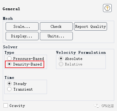
注:高超声速模拟通常选用密度基求解器。
”
4.2 Models设置
-
激活能量方程,选中选项Two-Temperature Model
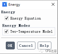
注:当使用基于密度的求解器时,双温度模型可用于模拟高超音速流动中的非平衡热现象。其模拟了流动中的能量弛豫过程,并提供了比单温度模型更好的流场预测。
”
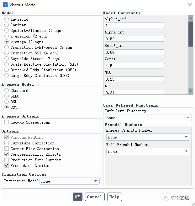
-
选择使用SST k-omega湍流模型,激活选项Compressibility Effects
4.3 Materials设置
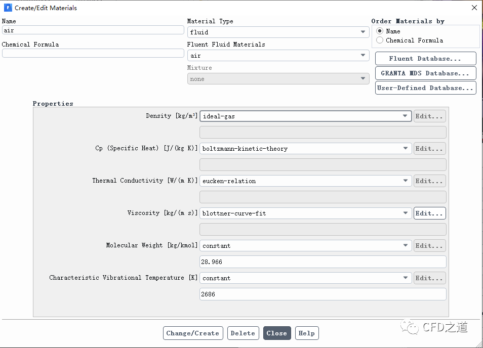
-
如下图所示指定空气的介质属性,修改 Density为ideal-gas,其他参数保持默认设置
4.4 操作条件设置
-
指定 Operating Pressure为0 Pa
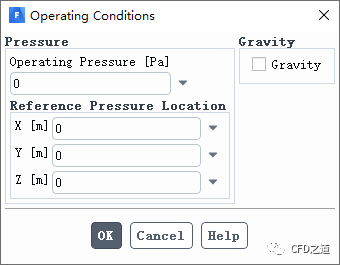
注:在流体介质选用理想气体模型时,常将操作压力指定为零,这样计算域中的压力为绝对压力。
”
4.5 边界条件设置
-
设置入口inflow的边界条件 -
指定 Gauge Pressure为25 Pa -
指定 Mach Number为17 -
指定 X-Component of Flow Direction为0.90630778 -
指定 Y-Component of Flow Direction为-0.42261826
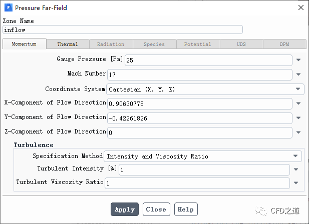
注:x方向分量为cos(-25°),y方向分量为sin(-25°)
”
-
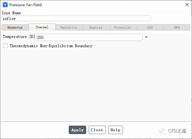
指定 inflow边界的温度为250 K
-
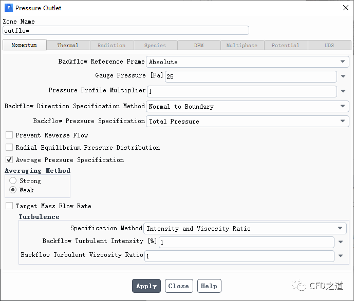
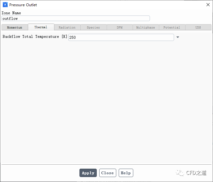
指定出口边界 outflow的边界条件 -
指定 Gauge Pressure为25 Pa -
激活选项 Average Pressure Specification,选择Averageing Method为Weak
-
指定出口回流温度为250 K
-
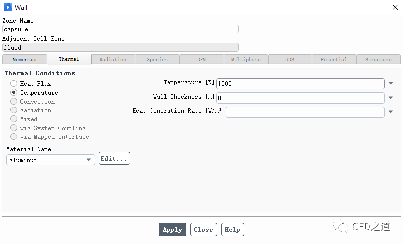
指定壁面 capsule的温度为1500 K
4.6 Methods
-
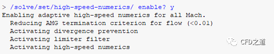
在TUI窗口中输入下面的命令以激活高速数值格式
/solve/set/high-speed-numerics/ enable? y
如下图所示。
-
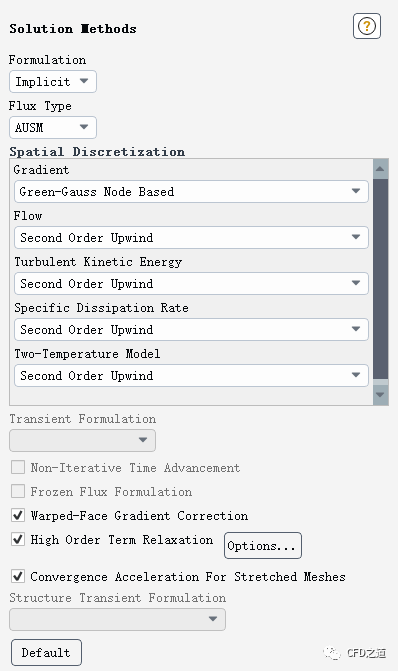
进入 Methods设置面板,如下图所示进行设置 -
指定 Formulation为Implicit -
指定 Flux Type为AUSM -
指定 Gradient为Green-Gauss Node Based -
激活选项 Convergence Acceleration For Stretched Meshes
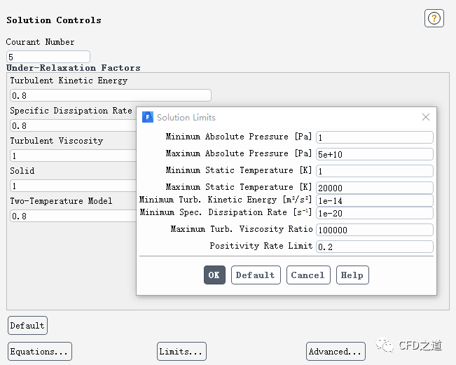
4.7 设置Controls
-
打开 Controls面板,点击Limits...按钮打开对话框 -
指定 Maximum Static Temperature为20000 K
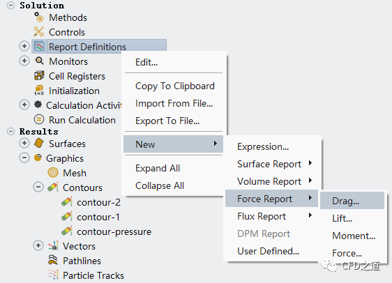
4.8 设置监测升阻力
-
右键选择模型树节点 Report Definitions,点击弹出菜单项New → Force Report → Drag…打开定义对话框
-
如下图所示设置阻力监测

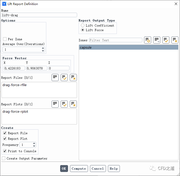
-
添加升力监测定义
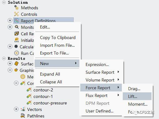
-
如下图所示设置参数
4.9 残差控制
-
如下图所示修改残差标准

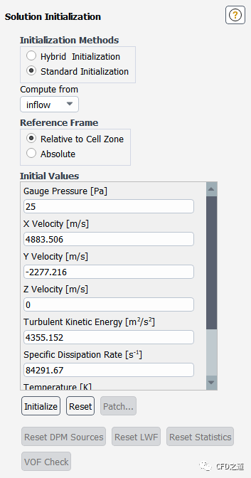
4.10 初始化
-
采用 Standard Initialization进行初始化 -
利用入口 inflow进行初始化
-
进行 fmg初始化设置及初始化,如下所示
solve/initialize/set-fmg-initialization

Customize your FMG initialization:
set the number of multigrid levels [5] 3
set FMG parameters on levels ..
residual reduction on level 1 is: [0.001]
number of cycles on level 1 is: [10] 200
residual reduction on level 2 is: [0.001]
number of cycles on level 2 is: [50] 400
residual reduction on level 3 [coarsest grid] is: [0.001]
number of cycles on level 3 is: [100] 1000
Number of FMG (and FAS geometric multigrid) levels: 3
* FMG customization summary:
* residual reduction on level 0 [finest grid] is: 0.001
* number of cycles on level 0 is: 1
* residual reduction on level 1 is: 0.001
* number of cycles on level 1 is: 200
* residual reduction on level 2 is: 0.001
* number of cycles on level 2 is: 400
* residual reduction on level 3 [coarsest grid] is: 0.001
* number of cycles on level 3 is: 1000
* FMG customization complete

set FMG courant-number [0.75] 0.25
enable FMG verbose? [no] yes

solve/initialize/fmg-initialization
Enable FMG initialization? [no] yes
注:对于高超声速流动,采用FMG初始化有利于提高收敛性。
”
4.11 计算
-
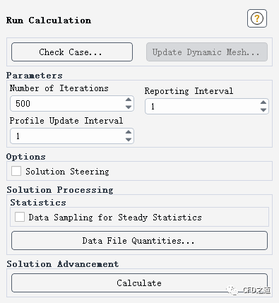
设置迭代 150次
-
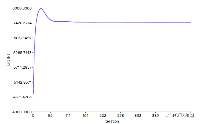
升力监测曲线如下图所示
-
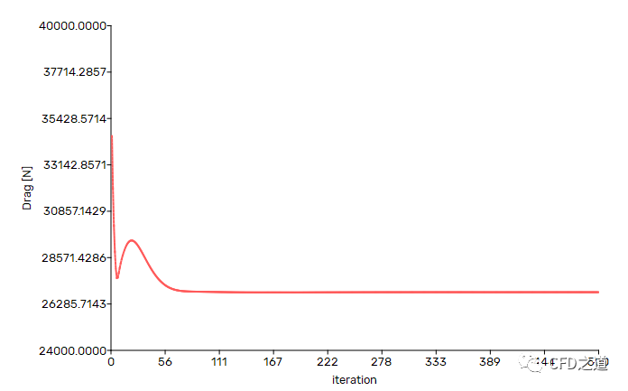
阻力监测曲线如下图所示
5 计算结果
-
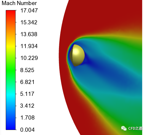
对称面上的马赫数分布
-
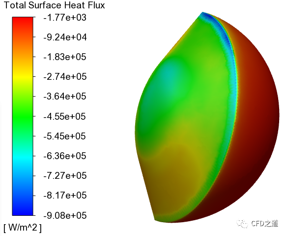
再入舱表面上热流密度如下图所示
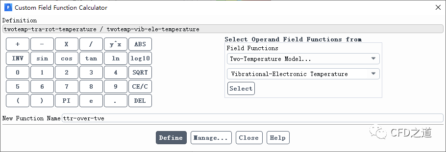
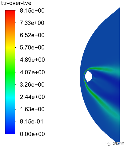
在对称平面上绘制平移旋转温度与振动电子温度的比值。这给出了流动中热不平衡区域的指示,这可以用双温度模型来考虑。
-
定义变量 ttr-over-tve,定义为平移旋转温度除以振动电子温度,如下图所示
-
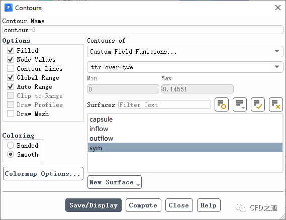
查看对称面上该物理量的分布
-
物理量分布如下图所示
相关文件:
链接:https://pan.baidu.com/s/1Qlsybx3rQ1OWcW37Ucps_Q 提取码:754g
”
本篇文章来源于微信公众号: CFD之道


评论前必须登录!
注册