
本案例演示利用Fluent Meshing中的FTM工作流进行自动泄漏修补的操作流程。
1 导入几何模型
-
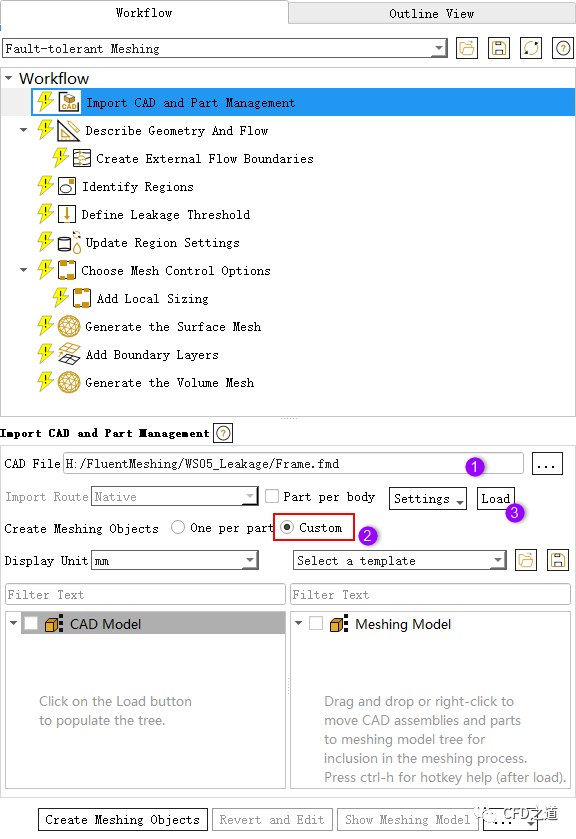
选择节点Import CAD and Part Management,按下图所示操作顺序设置参数
-
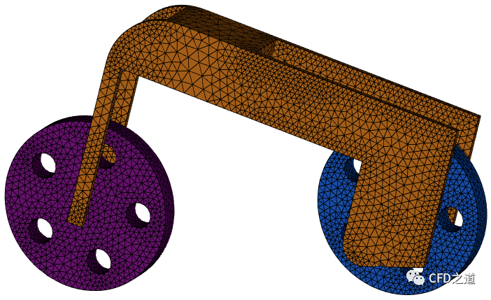
选中图中所示的部件(wheel-front、wheel-rear、frame),利用鼠标将其拖拽到右侧列表框中
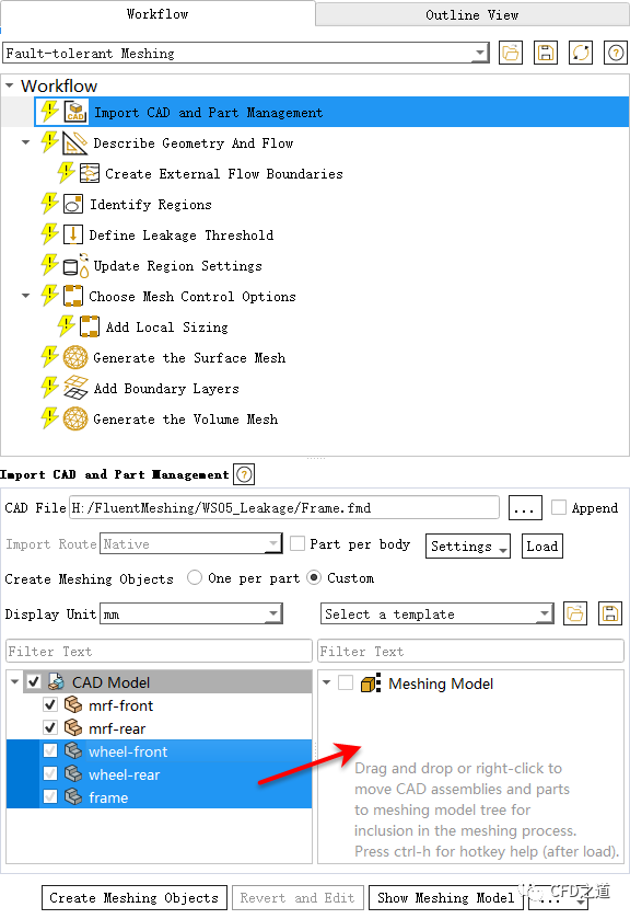
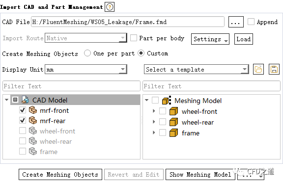
拖拽完毕后如下图所示。
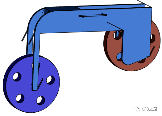
几何模型如下图所示。
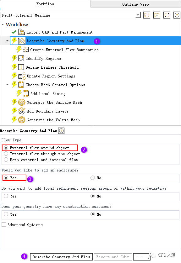
2 描述几何
-
选中模型树节点Describe Geometry And Flow,如下图所示顺序选择想要的选项
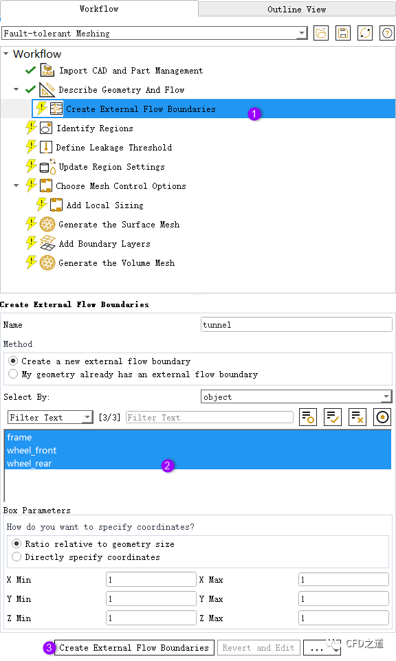
3 创建外部边界
-
选择模型树节点Create External Flow Boundaries,如下图所示选中所有部件并设置计算区域的大小
注:
注:实际计算中,需要设置外部区域足够大。本案例仅为功能演示,并未将计算区域设置得足够大。
”
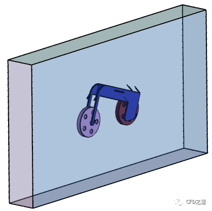
生成外部区域如下图所示。
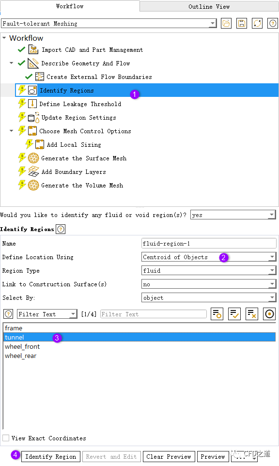
4 识别计算区域
-
选择节点Identify Regions,选择利用tunnel创建材料点
5 定义泄漏阈值
-
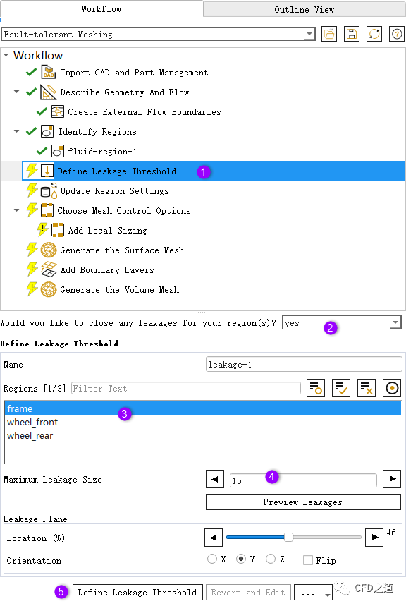
选择模型树节点Define Leakage Threshold,如下图所示顺序设置参数进行泄漏检测
6 更新区域
-
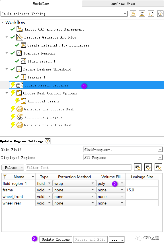
点击模型树节点Update Region Settings,如下图所示设置参数
注:
注:这里设置计算区域体网格为poly多面体网格,这需要开启beta功能才行。默认情况下生成hexa-core网格。
”
7 生成面网格
-
Choose Mesh Control Options节点下采用默认参数 -
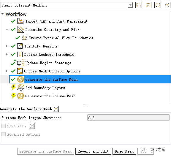
Generate the Surface Mesh节点采用默认参数,并生成面网格
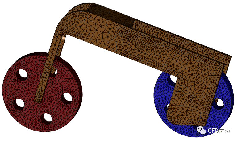
查看固体壁面上的计算网格,如下图所示,可以看到狭缝被去除了。
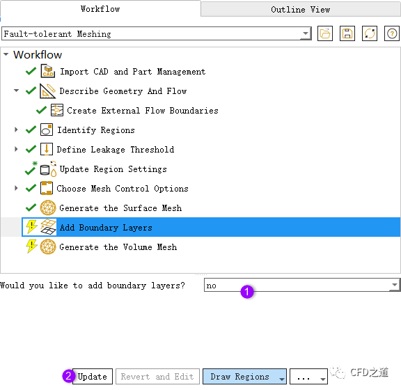
8 体网格生成
-
边界层参数采用默认设置
-
采用默认参数生成体网格
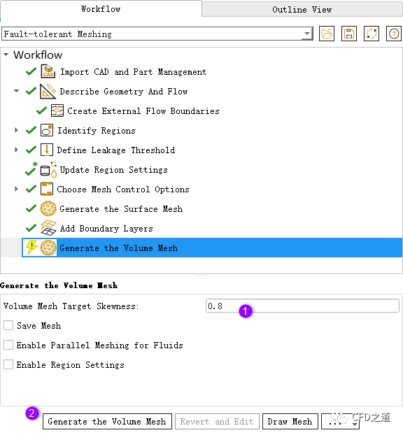
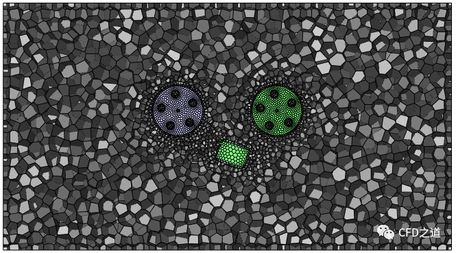
生成体网格如图所示。
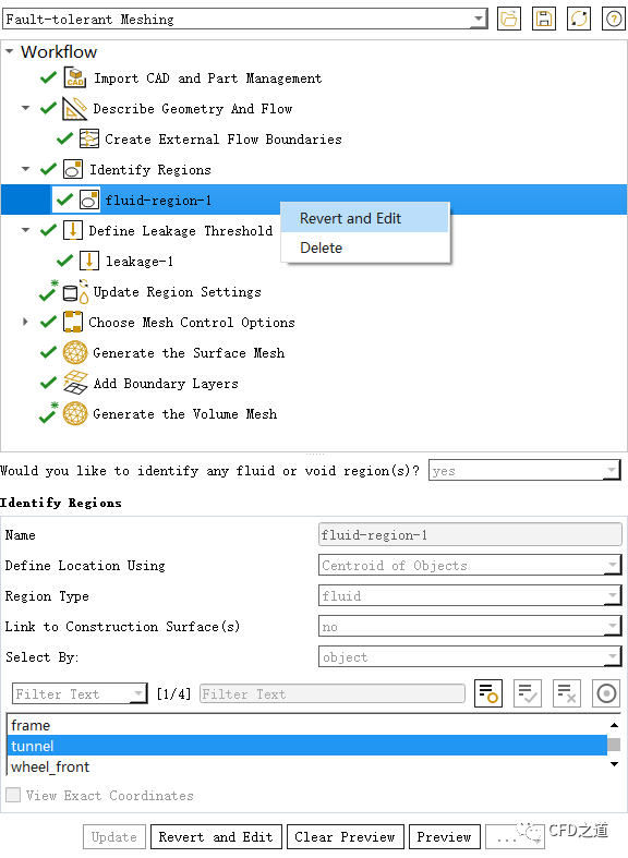
9 另一种方法
上面采用的是利用流体域材料点进行泄漏检测计算区域,下面利用void区域材料点创建计算区域。
-
右键选择节点fluid-region-1,点击弹出菜单项Revert and Edit取消设置
-
选中节点Identify Regions,采用图中参数创建void区域
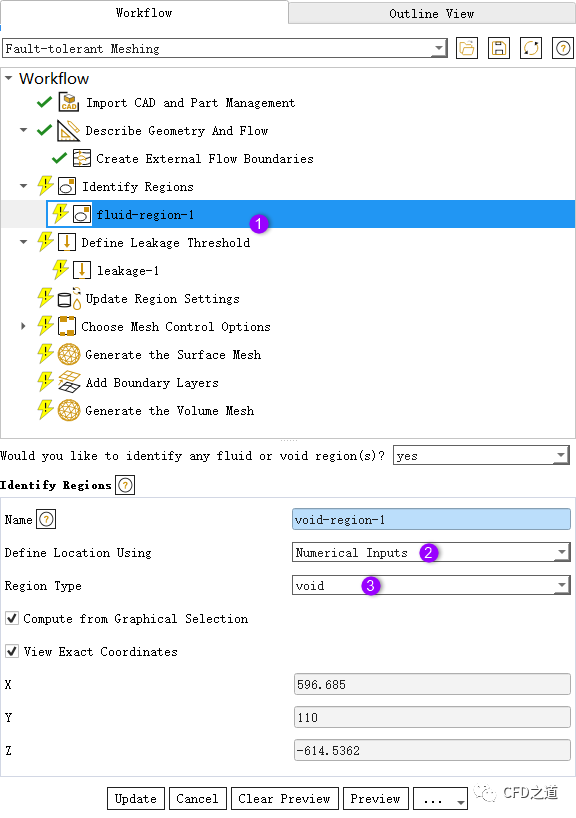
注:
注:图中标识有误,应当是选中identify regions节点再新建一个void区域。
”
-
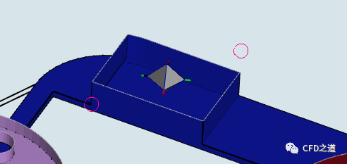
选中如下图所示区域上的两个节点,确保材料点位于图中所示位置
-
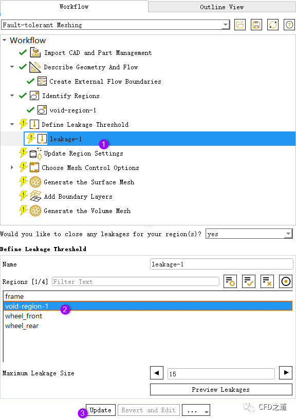
泄漏检测时选择void区域,如下图所示
-
更新面网格
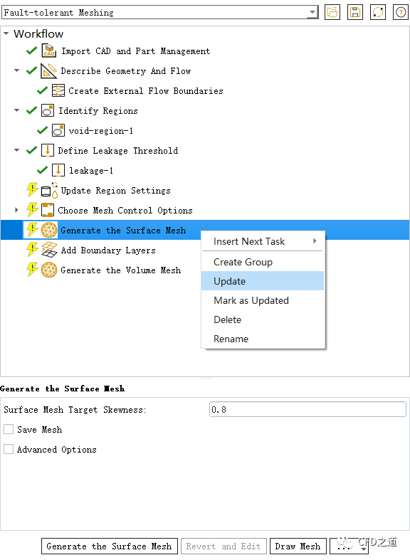
生成面网格如下图所示,可以看到横梁上的缺陷几何已经被清理掉了。
后续的体网格划分过程就不再赘述。
相关文件下载:
注:
链接:https://pan.baidu.com/s/1wef4bi2bsWvwRaExl8EQsA 提取码:hlc9
”
本篇文章来源于微信公众号: CFD之道


评论前必须登录!
注册