
本文演示利用Fluent Meshing中FTM工作流在尺寸控制方面的应用。
-
启动Fluent Meshing
1 导入几何
-
选择使用Fault-tolerant Meshing工作流 -
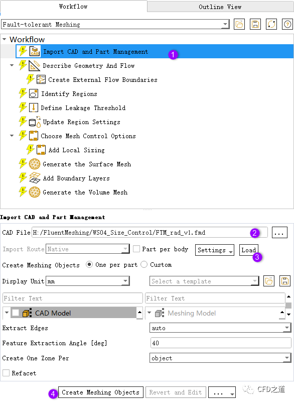
选中模型树节点Import CAD and Part Management,如下图所示导入模型文件FTM_rad_v1.fmd
注:
注:fmd文件可以在scdm中导出。这里也可以直接导入scdoc文件。
”
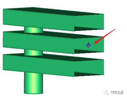
导入的几何模型如图所示。
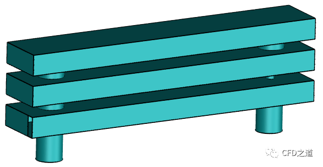
几何模型中存在破损的面,需要在后续环节需要修补。
注:
建议:对于简单几何模型,建议在scdm中清理完毕后再使用Fluent Meshing进行网格生成。本案例仅为演示FM的功能。
”
2 描述几何
-
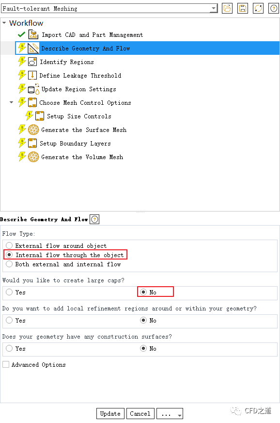
选择模型树节点Describe Geometry And Flow,如图所示选择相应的选项
3 识别区域
-
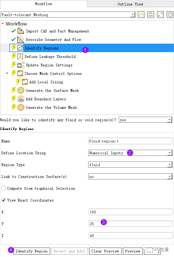
选中模型树节点Identify Regions -
选择Define Location Using为Numerical Inputs -
如下图所示设置坐标为**(150 25 40)** -
点击按钮Identify Region识别计算区域
-
可以预览输入的坐标点,确保其位于计算区域的内部
注:
注:确保创建的材料点位于几何模型的内部。
”
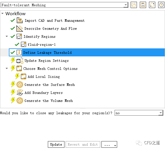
4 定义leakage
-
鼠标点击模型树节点Define Leakage Threshold,采用默认设置
注:
注:这里先不进行泄露检测,目的只是为了测试此功能。
”
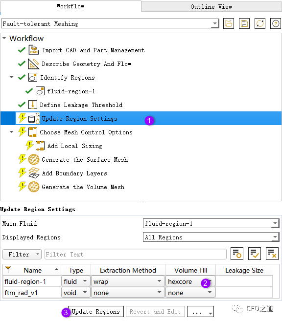
5 更新区域
-
选择模型树节点Update Region Settings,如下图所示设置
注:
注:在这里可以指定流体区域的体网格类型,Fluent Meshing提供了hexcore、polyhedra及poly-hexcore,默认为hexcore,另外两种类型的体网格生成需要开启beta模式。
”
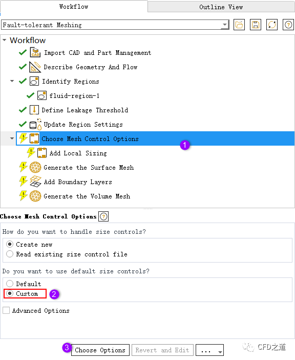
6 尺寸控制
-
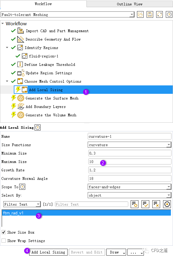
选中模型树节点Choose Mesh Controls Options,如下图所示设置选项Custom,点击按钮Choose Options
-
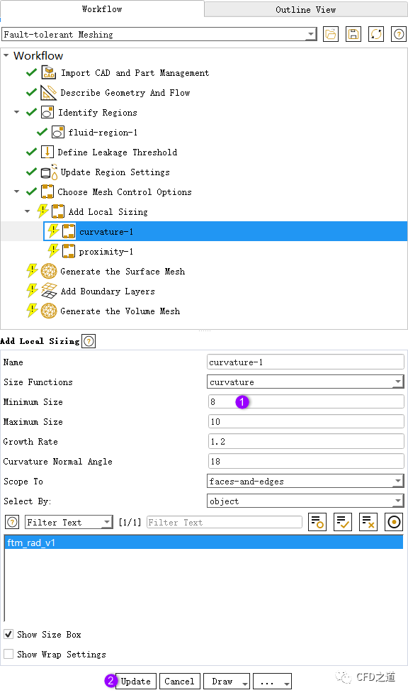
如下图所示创建一个curvature尺寸分布
-
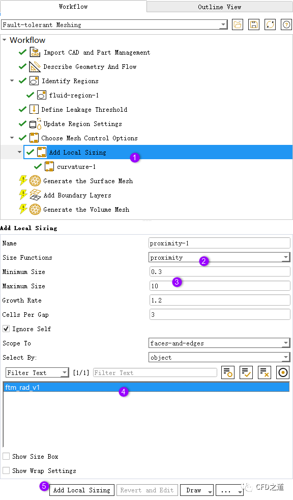
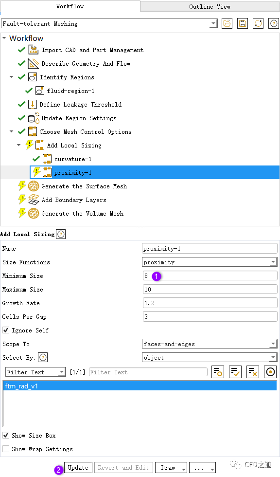
创建另一个proximity尺寸分布,如下图所示
7 生成面网格
-
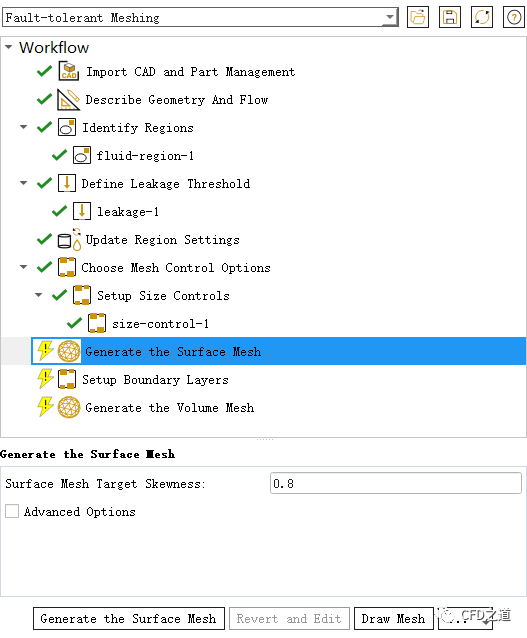
选中模型树节点Generate the Surface Mesh,设置Surface Mesh Target Skewness为0.8 -
点击按钮Generate the Surface Mesh生成面网格
生成的面网格如图所示。
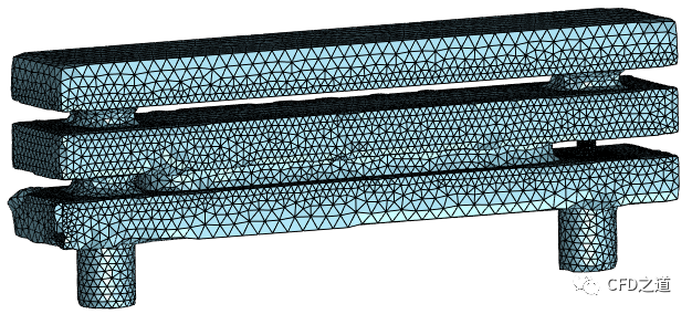
由于几何面存在缺失,导致抽取的流体区域存在缺陷。注意图中的缺陷位置。
8 改变网格控制参数
尝试改变网格尺寸参数来改善面网格质量。
-
右键选择模型树节点size-control-1,点击弹出菜单项Revert and Edit
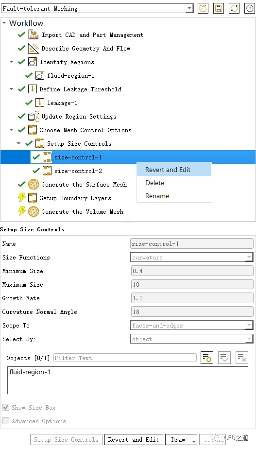
-
设置参数Minimum Size为8
-
设置proximity-1的最小尺寸为8
-
重新生成面网格

-
生成的面网格如下图所示
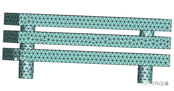
面网格有所改善,由于设置最小尺寸为8 mm,导致几何模型中小于8mm的几何特征被清理,因此面网格中小的圆柱面被删除。而网格尺寸太大,导致曲面上网格质量较差。
通过控制全局网格尺寸,难以解决几何孔洞问题。
9 修改参数
-
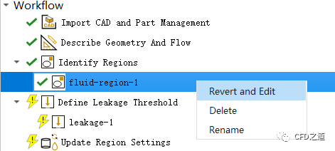
右键选择模型树节点fluid-region-1,选择Revert and Edit
-
选中Identify Regions,如下图所示创建一个void区域用于后面的泄漏检测
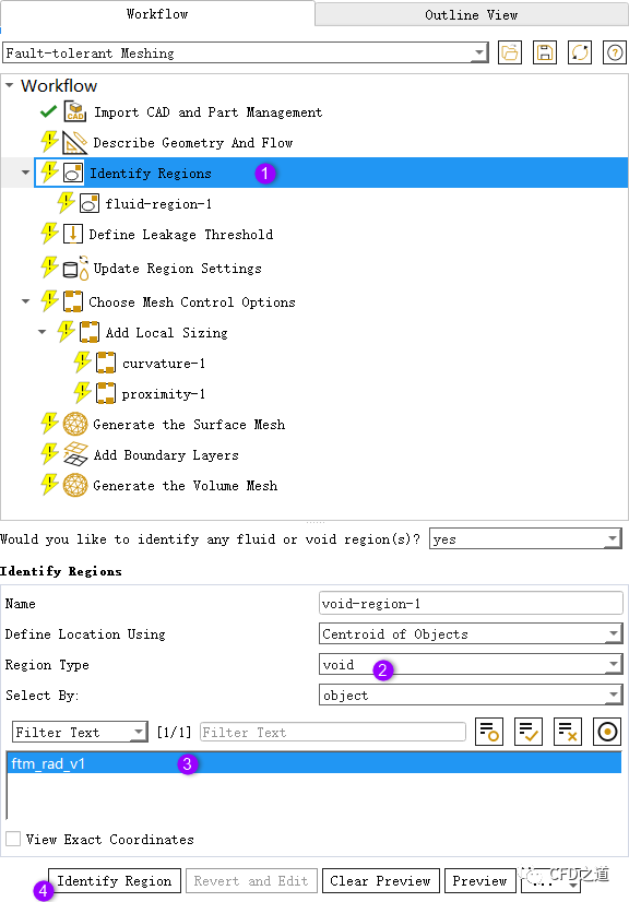
注:
注:这里创建一个在计算区域外部的材料点
”
-
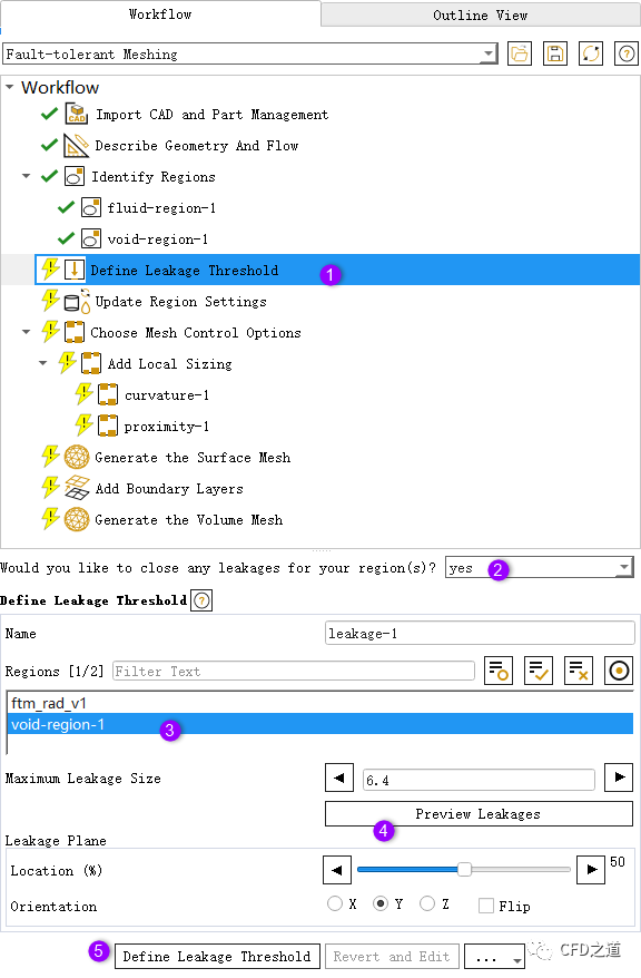
选择节点Define Leakage Threshold,如下图所示选中列表项void-region-1,采用默认参数
-
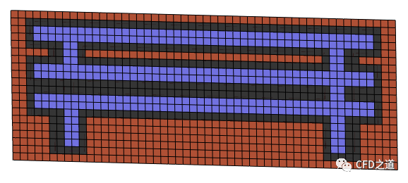
可以点击按钮Preview Leakages查看计算域抽取情况,如下图所示明显抽取了两个计算区域
-
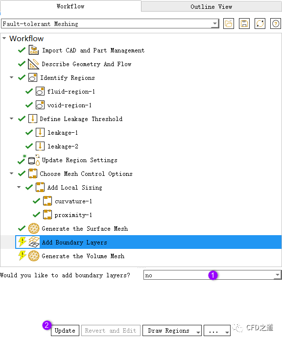
选择节点Add Boundary Layers,设置不生成边界层网格
-
选择节点Generate the Volume Mesh,设置最大歪斜率0.9,如下图所示生成体网格
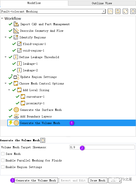
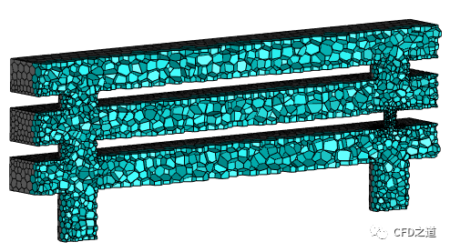
最终生成体网格如下图所示,图中为剖面上的网格。
链接:https://pan.baidu.com/s/1yYW3DDE9OIq4XGrk2D7NCQ 提取码:e70f
”
本篇文章来源于微信公众号: CFD之道


评论前必须登录!
注册