本案例利用Polyflow计算气体通过多孔介质区域的流场分布。
1 问题描述
考虑如下图所示的流动,计算区域由两个方向不同的多孔介质区域组成,其中上面区域角度为120°,下方区域角度为30°。
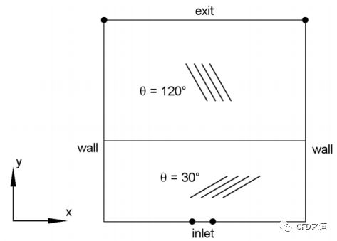
两个多孔介质区域均具有各向异性渗透性能。在笛卡尔坐标系(x,y)中,两层材料的渗透性用张量K表示,分别给出如下:
(1)区域I

(2)区域II

两区域内孔隙率均为0.3。两种介质的高度分别为2米和3米,宽度均为5米,气体粘度2E-5 Pa.s。
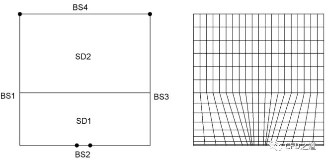
计算网格如下图所示。计算域包含两个子区域,每个子域对应一种多孔介质。计算区域中包含4个边界:左侧壁面(BS 1)、入口(BS 2)、右侧壁面(BS 3)和出口(BS 4)。入口边界宽度为0.5 m,指定压力为1.5e5 Pa。
2 Polyflow设置
2.1 创建Task
-
Read a mesh: darcy.msh -
Create a new task: 2D planar geometry, steady-state (default)
2.2 创建子任务
-
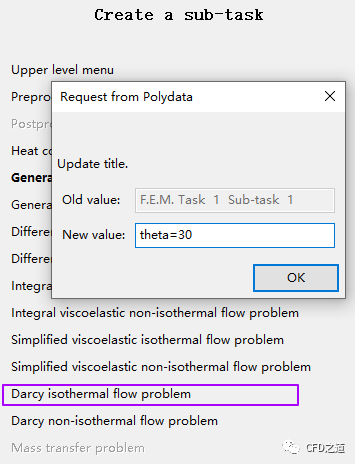
Create a sub-task: Darcy isothermal flow problem -
Title: theta=30
-
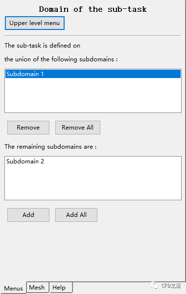
Domain of the sub-task: Subdomain 1
2.3 定义材料参数
鼠标双击模型树节点Material data进入材料编辑面板
-
点击选项Porous media and fluid viscosity
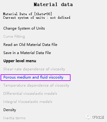
-
选择选项Switch to tensor mode
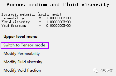
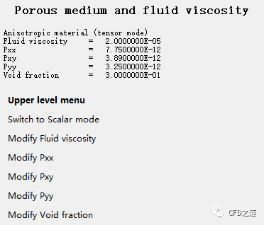
设置材料参数:
-
fluid viscosity: 2E-5 -
Pxx: 0.775E-11 -
pxy: 0.389E-11 -
pyy: 0.325E-11 -
void fraction: 0.3
2.4 定义边界条件
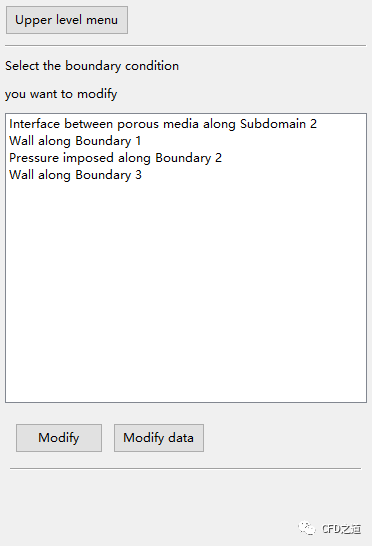
鼠标双击模型树节点Pressure boundary conditions设置边界条件。
-
S2: Interface between porous media -
BS1: Wall -
BS2: Pressure imposed,P=1.5E5 -
BS3: Wall
2.5 创建子任务
-
Create a sub-task: Darcy isothermal flow problem -
Title: theta=120 -
Domain of the sub-task: Subdomain 2
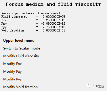
2.6 修改材料参数
双击模型树节点Material data进入材料设置面板
-
选择选项Porous media and fluid viscosity
-
选择选项Switch to tensor mode
设置材料参数:
-
fluid viscosity: 2E-5 -
pxx: 0.325E-11 -
pxy: -0.389E-11 -
pyy: 0.775E-11 -
void fraction: 0.3
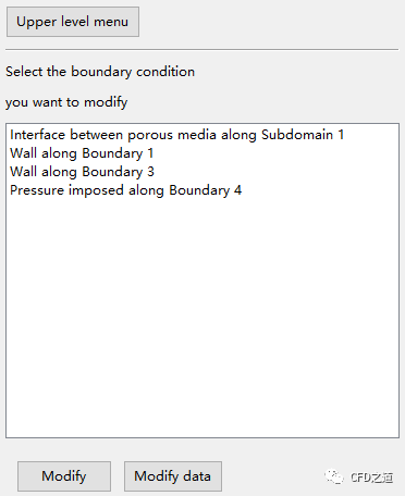
2.8 定义边界条件
鼠标双击模型树节点Pressure boundary conditions
-
S1: Interface between porous media -
BS1: Wall -
BS3: Wall -
BS 4: Pressure imposed,P = 0
2.9 定义输出
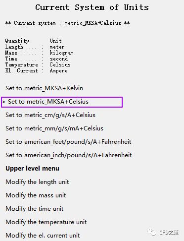
鼠标双击模型树节点Outputs,设置计算单位。
-
System of units for CFD-Post: metric_MKSA+Celsius
-
Save and Exit
3 计算结果
-
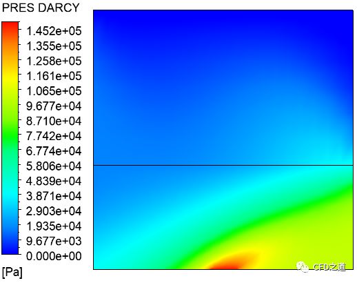
压力分布
-
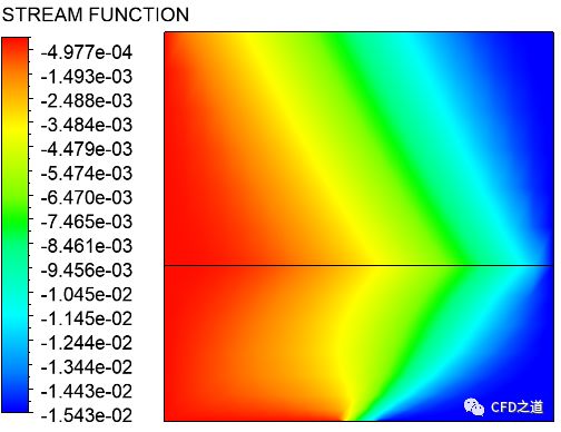
流函数分布
-
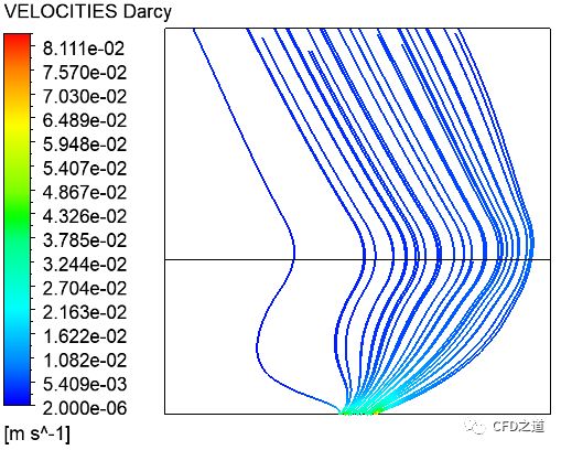
流线分布
本篇文章来源于微信公众号: CFD之道


评论前必须登录!
注册